317Hardware
Greenhouse Monitoring System
Capstone Project - Greenhouse Monitoring System
November 26, 2019 - Presentation Due
PowerPoint presentation slides have been posted in the presentation folder.
I will be presenting this next week.
November 23, 2019 - Programming pdate
I updated my sample Python program to include functionality for the watering level switch and irrigation/motor system. You can find the updated program under software/readingsupdated.py
Here is the code fragment:
 # Print the ADC values.
    print('| {0:>6} | {1:>6} | {2:>6} | {3:>6} |'.format(*values))

    # Declare variable for watering level switch
    water_lvl = 0

    # Declare variable for moisture reference value
    ref = 13000

    # Set watering level
    if (values[1] < 1000):
	water_lvl = 0.5
    elif (values[1] > 12000 and values[1] < 14000):
	water_lvl = 1.5
    elif (values[1] > 24000):
	water_lvl = 3
    else:
	water_lvl = 1

    # Turn on motor/watering system if soil moisture is too low
    if (values[0] > ref):
        GPIO.output(22,GPIO.HIGH)
        # Turn motor on for water_lvl seconds
	   time.sleep(water_lvl)
        GPIO.output(22,GPIO.LOW)
        # sleep to allow water absorbtion before recheck
	   time.sleep(10)

    # Pause for 2 seconds.
    time.sleep(2)
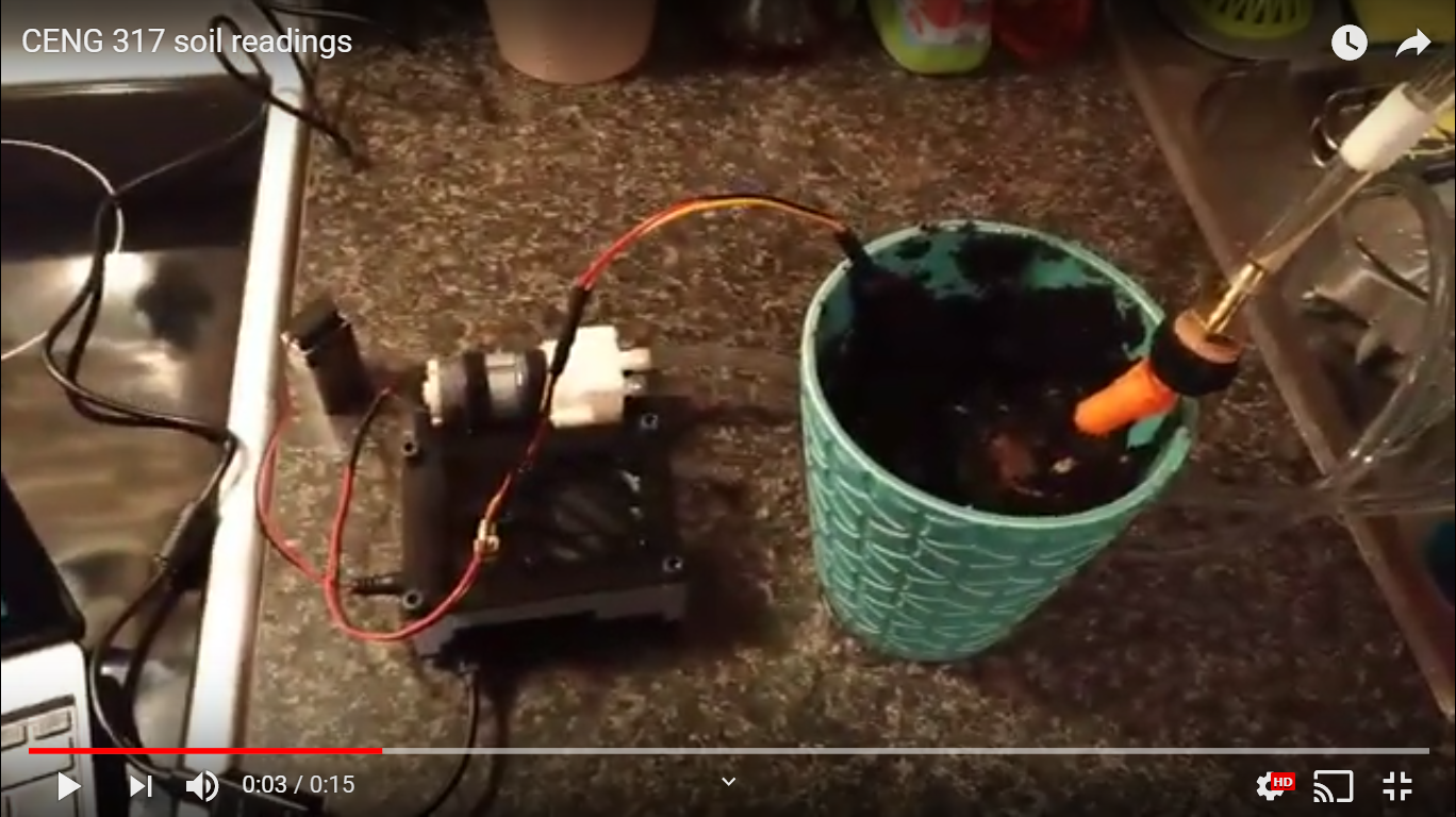
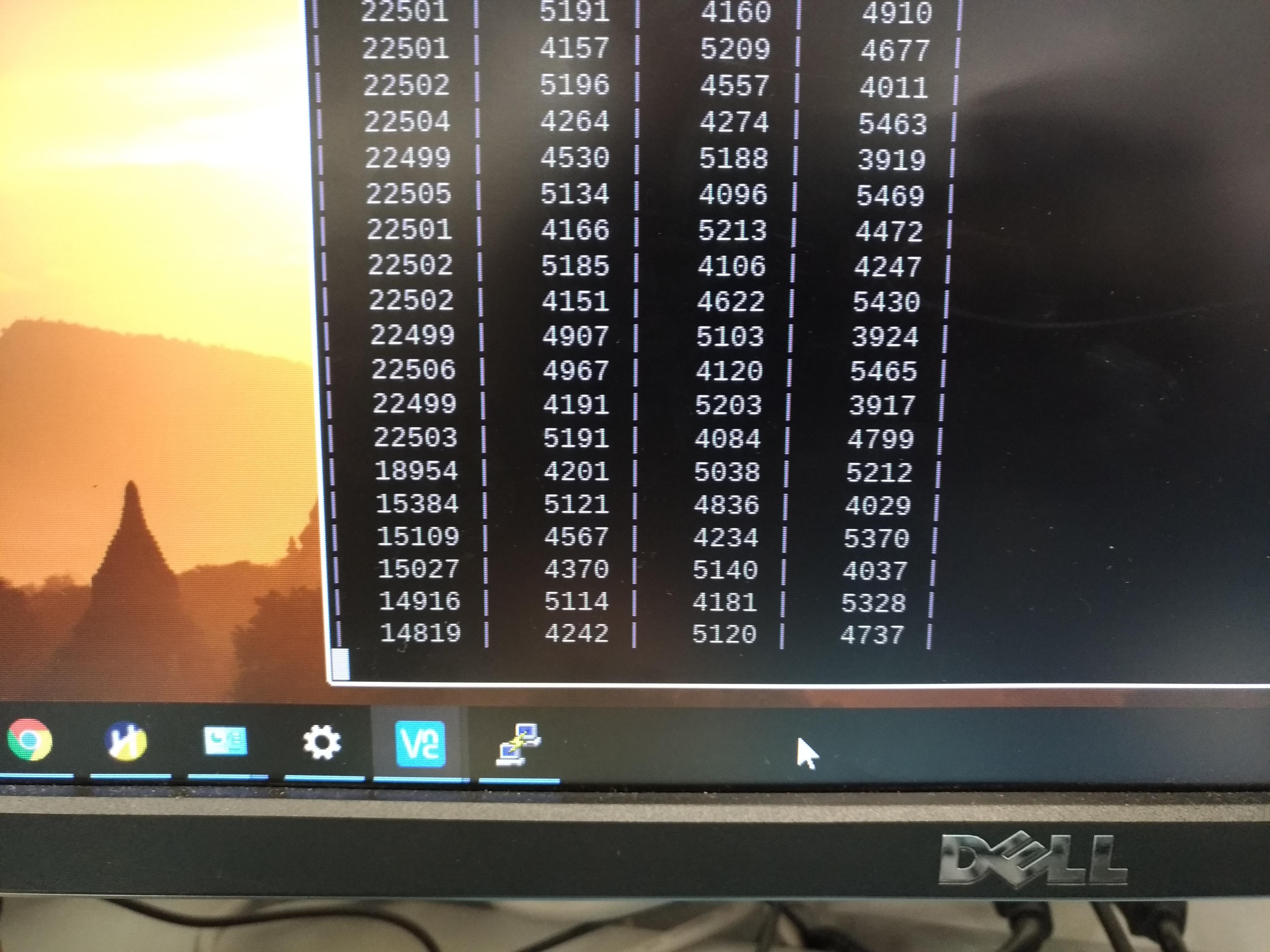
Video of the fully functioning system (watering level is set to “medium” or 1.5 seconds):
November 22, 2019 - Hardware Update
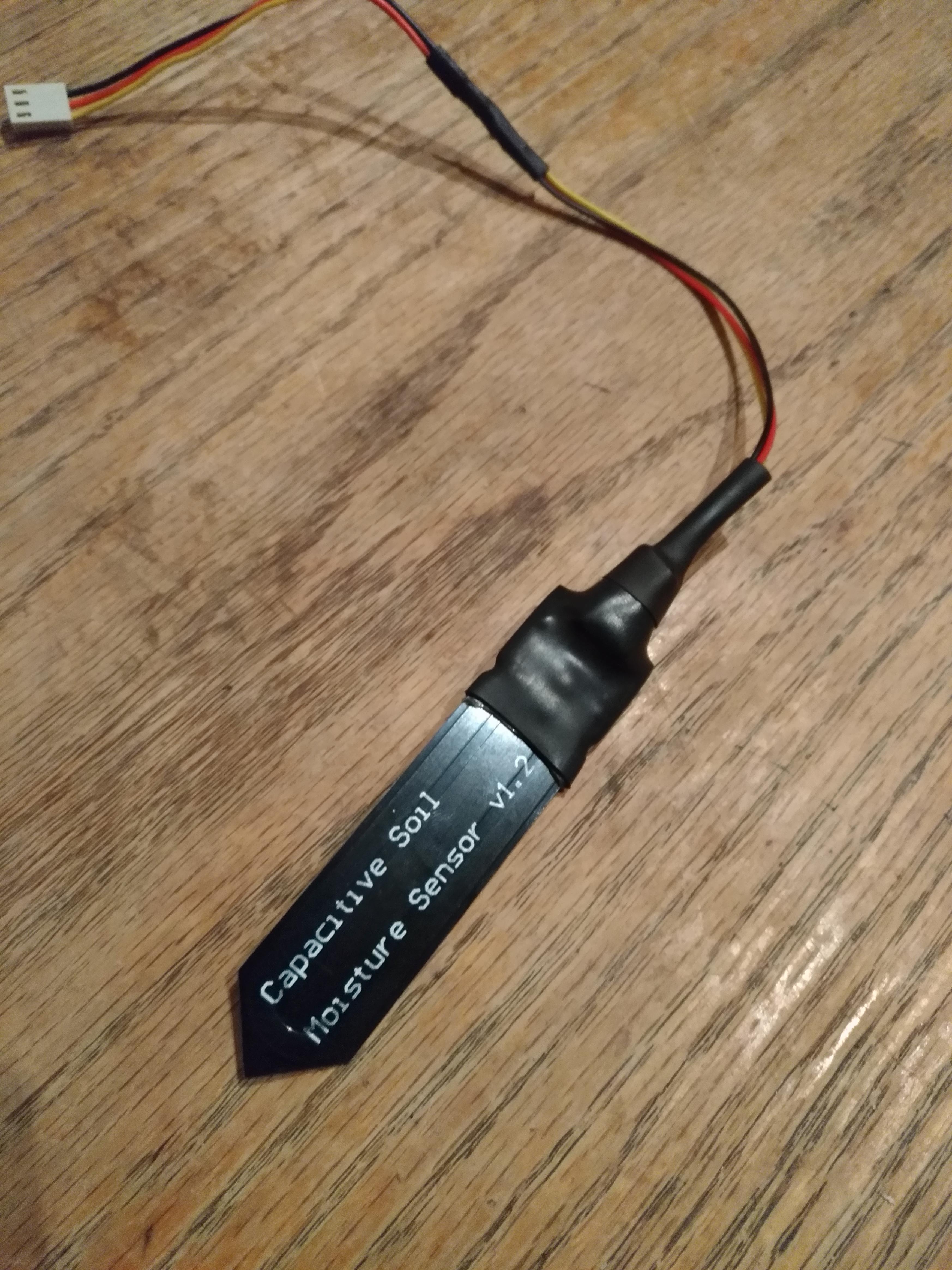
Heat shrink to protect sensor electronics:
November 19, 2019 - Enclosure Due
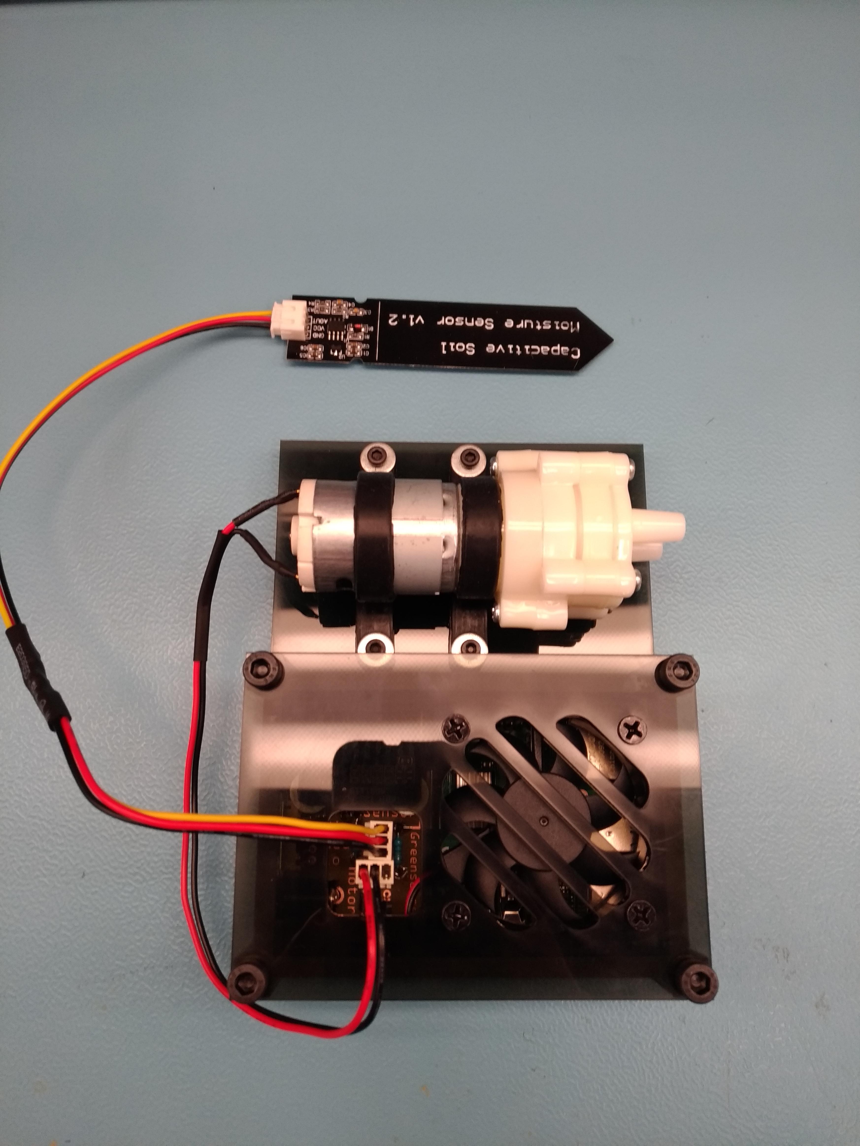
Completed enclosure assembled:
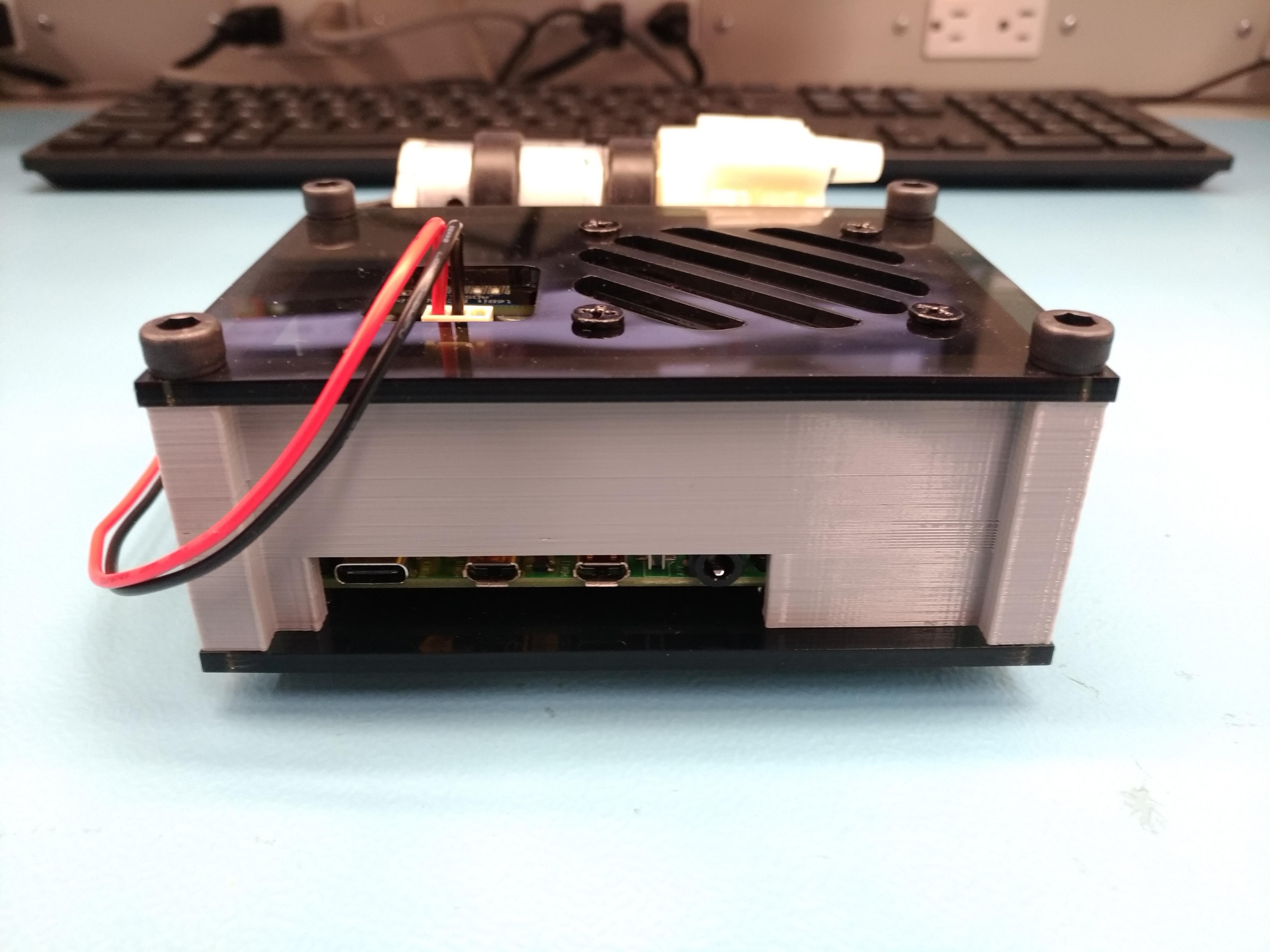
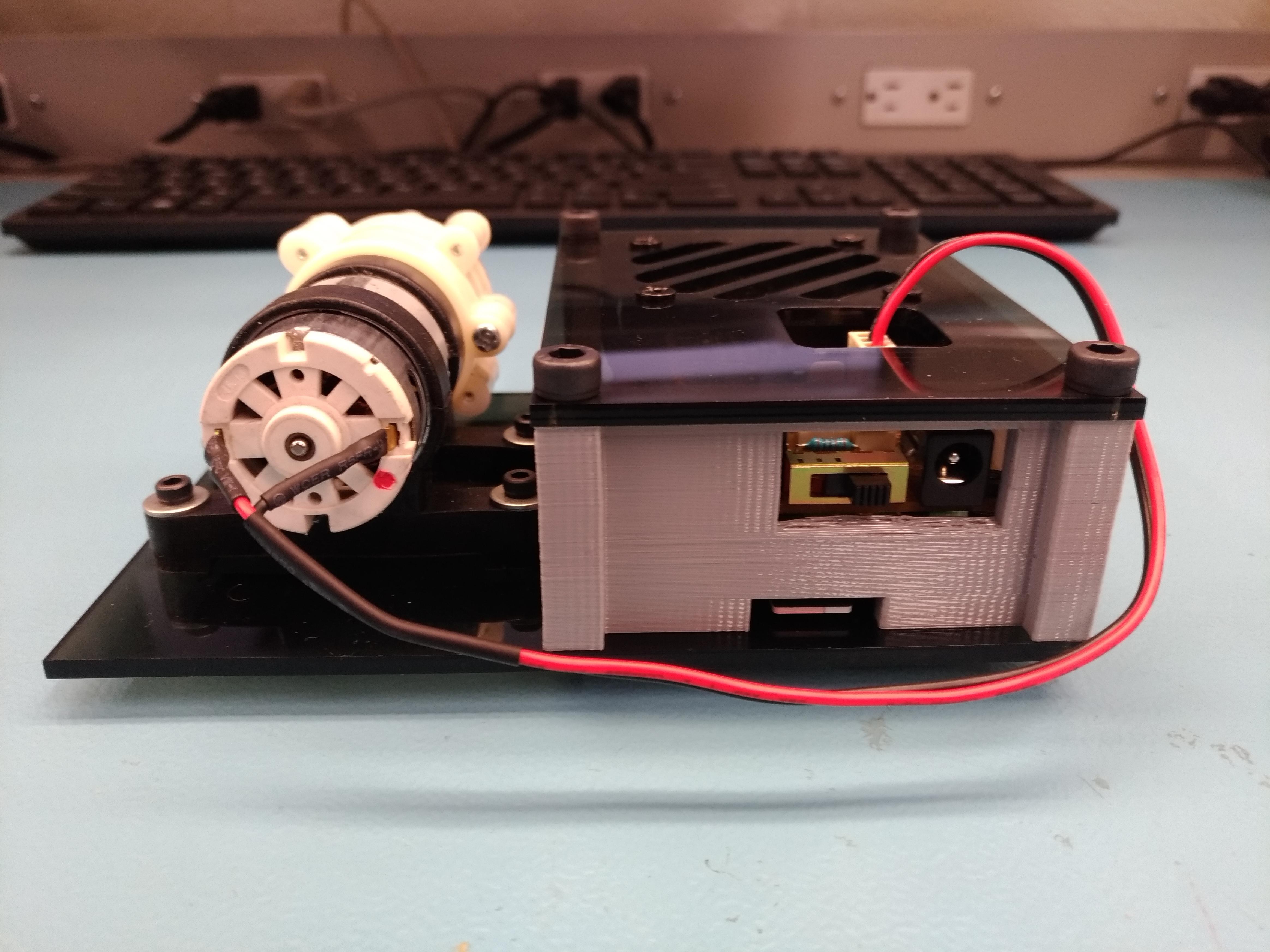
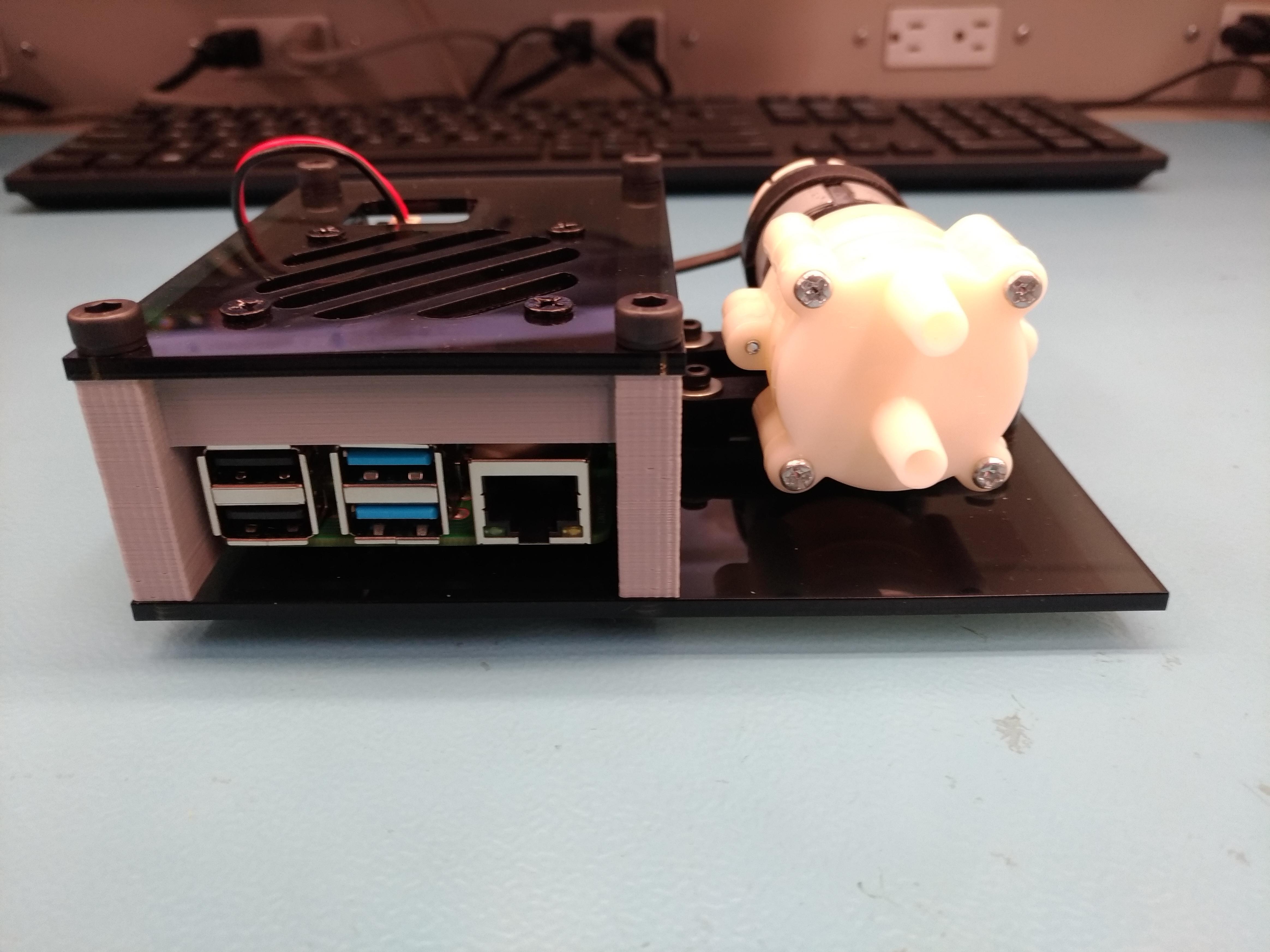
All measurements/tolerances for this case (3D print parts or laser cut parts) were obtained using a vernier caliper or taken from this Pi 4 blueprint. This case was custom designed by myself.
November 14, 2019 - Case Parts
I received all my case parts today. The 3D printed middle section, acrylic top/bottom, acrylic washers, and hardware for assembly. I will be stopping by my old workplace to tap the holes on the bottom cover.
The hardware I picked up (no cost):
(4) M5 x 0.8 x 40mm socket head screw
(4) M3 x 0.5 x 16mm socket head screw
(4) M3 x 0.5 nuts
(4) M2.5 x 0.45 x 10mm button head screw
Already owned:
(4) computer case fan screws
(4) M3 washers
(4) 3mm thick acrylic washers for under the Pi (so it doesn’t rest on its pins)
Pics of individual parts to be posted…
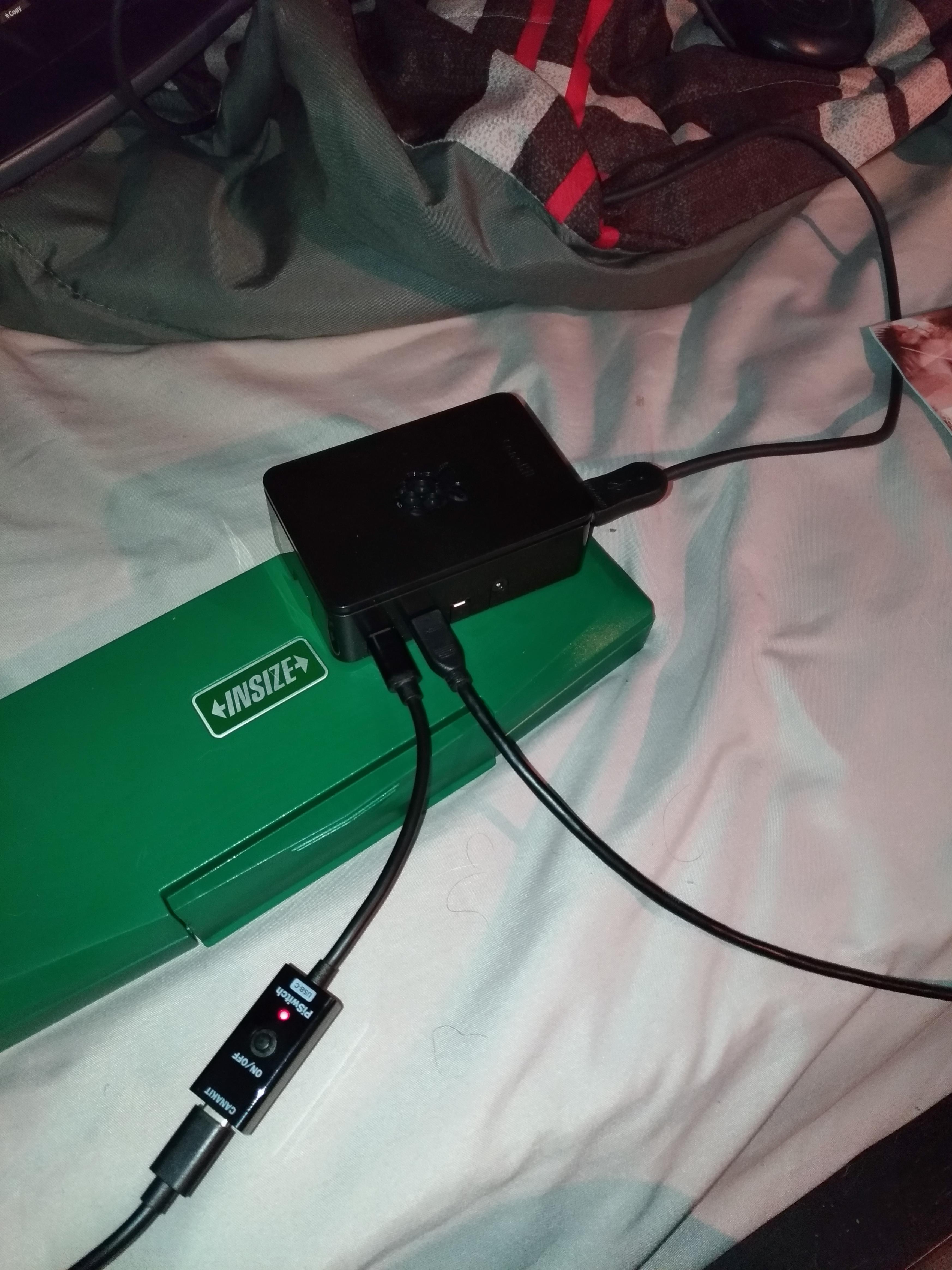
November 12, 2019 - PCB Power Up
Today during the lab I installed my completed PCB onto the Pi and demonstrated reading sensor values to the professor.
I also submitted my week 10 progress report.
Later that day I designed the top and bottom covers for my case. These designs were created in CorelDraw and will be laser cut out of acrylic.
Top cover: Includes intake slots for the fan and a cutout for the molex connectors.
Bottom cover: Motor will be mounted to this as well (beside the Pi).
November 11, 2019 - Enclosure Design
I designed the middle section of my case which will be enclosed by acrylic plates on the top and bottom. I created this design from scratch using OpenSCAD. This piece has been sent out for 3D printing.
View 1:
Front cutout - USB and ethernet ports, Side cutout - USB-C power, HDMI, and audio ports
.png)
View 2:
Bottom cutout - Pi SD card access, Top cutout - access to switch and DC jack on PCB
.png)
November 8, 2019 - Progress Update
Over the weekend I powered up my PCB and got readings from it. I also did some finish wiring/soldering on some components.
PCB power up readings (first 2 columns):
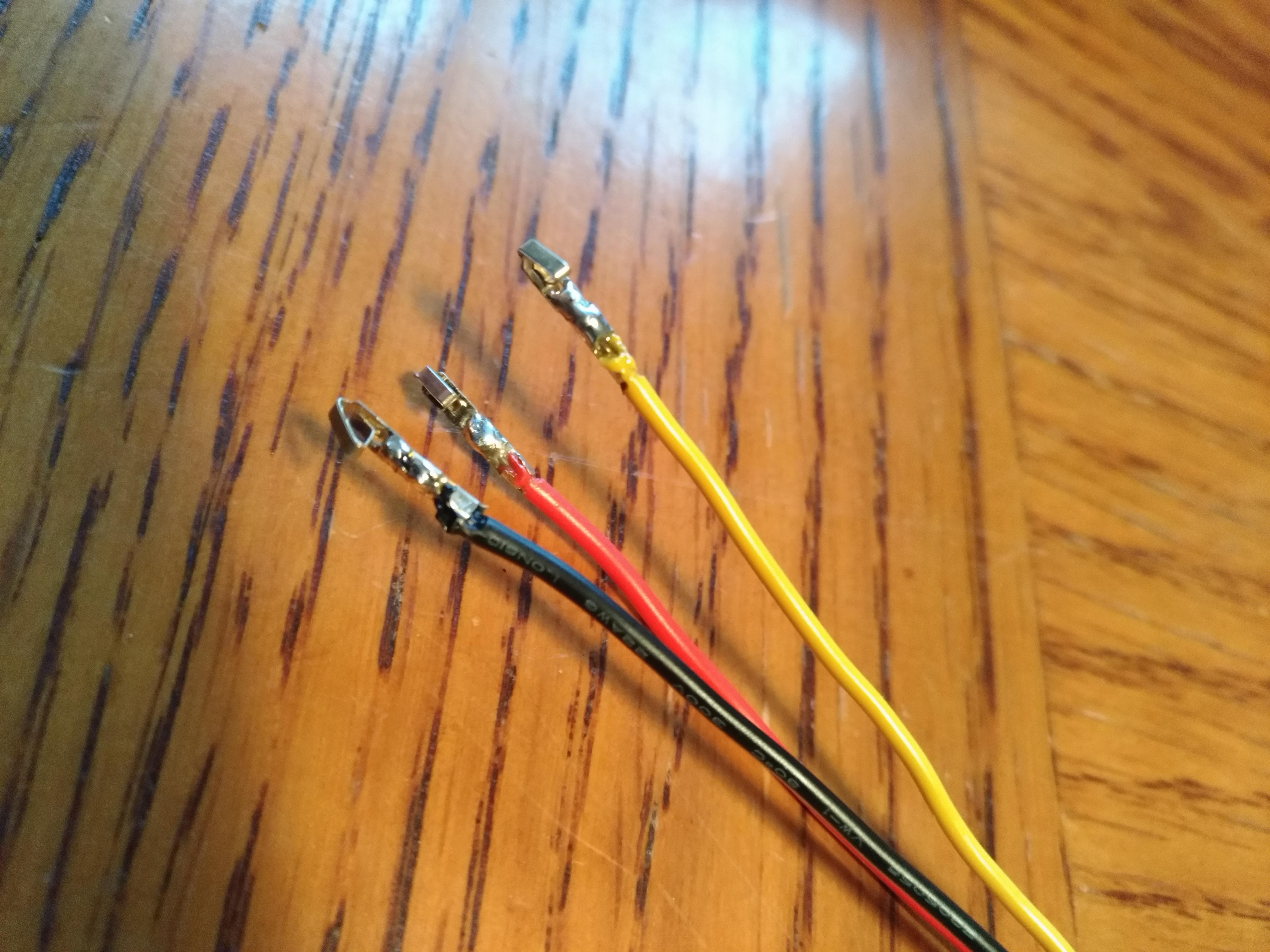
Extend sensor wires:
Crimp/solder pins for molex connector:
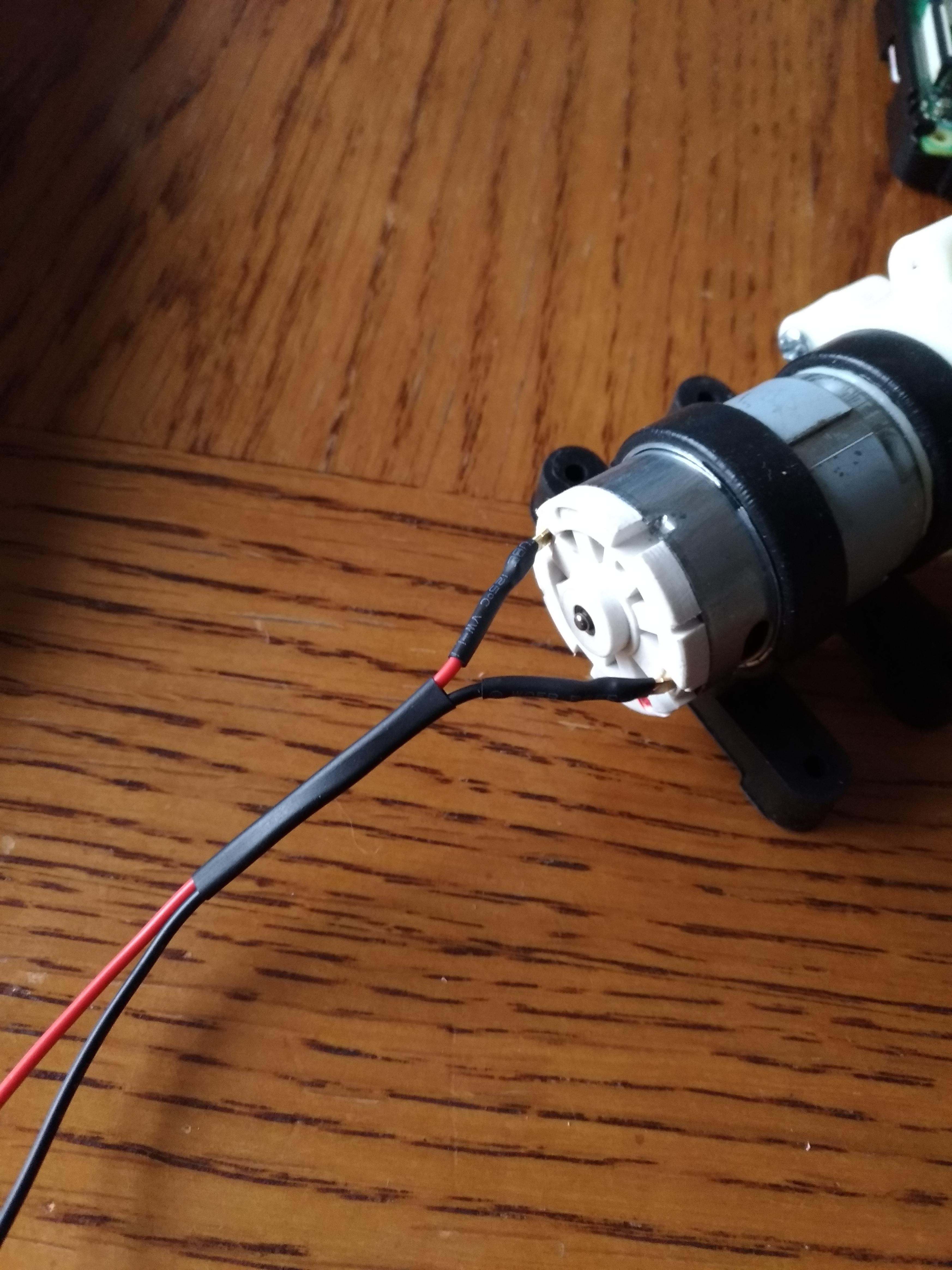
Soldered a pigtail onto the motor:
November 5, 2019 - PCB Soldered
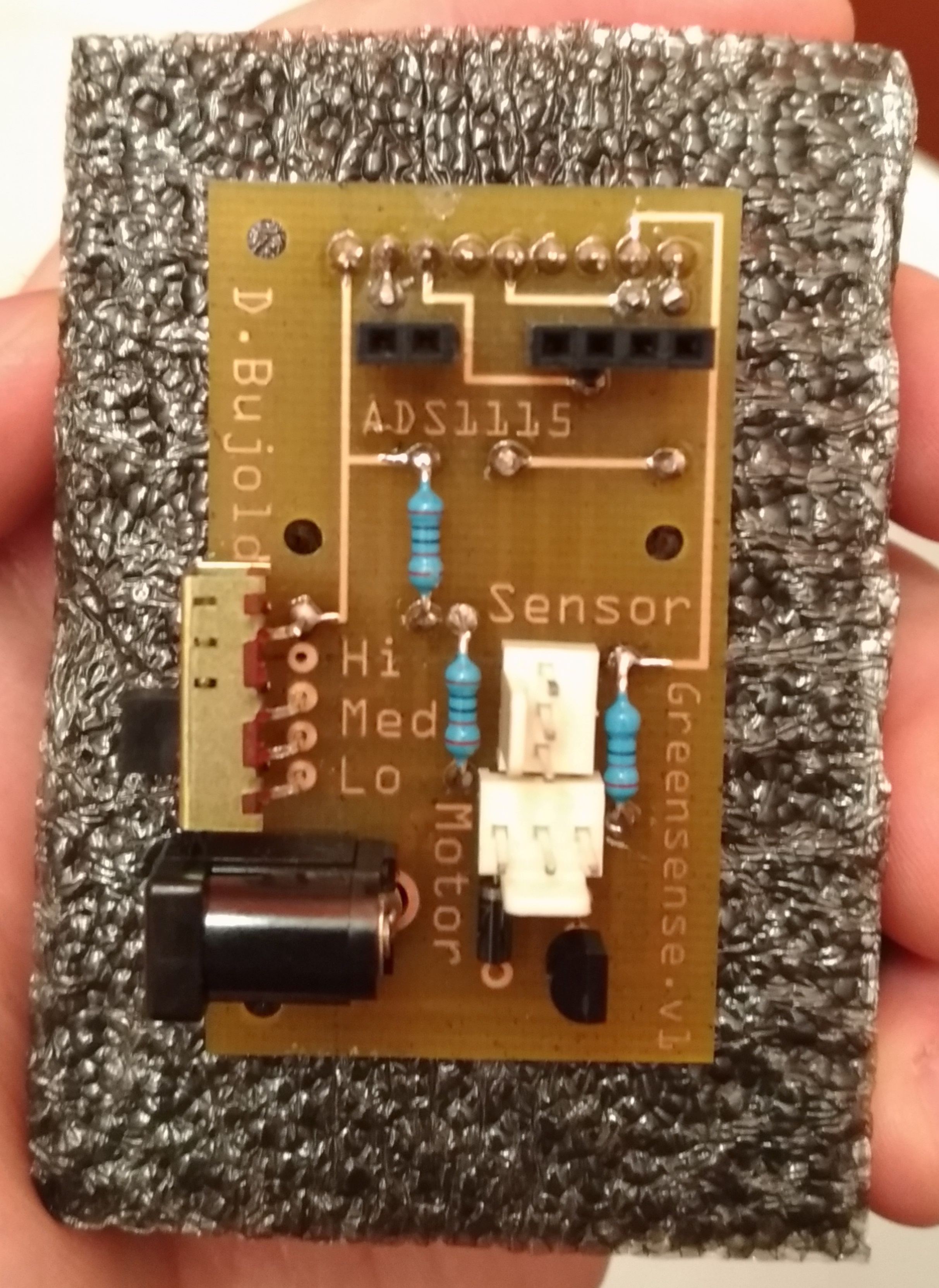
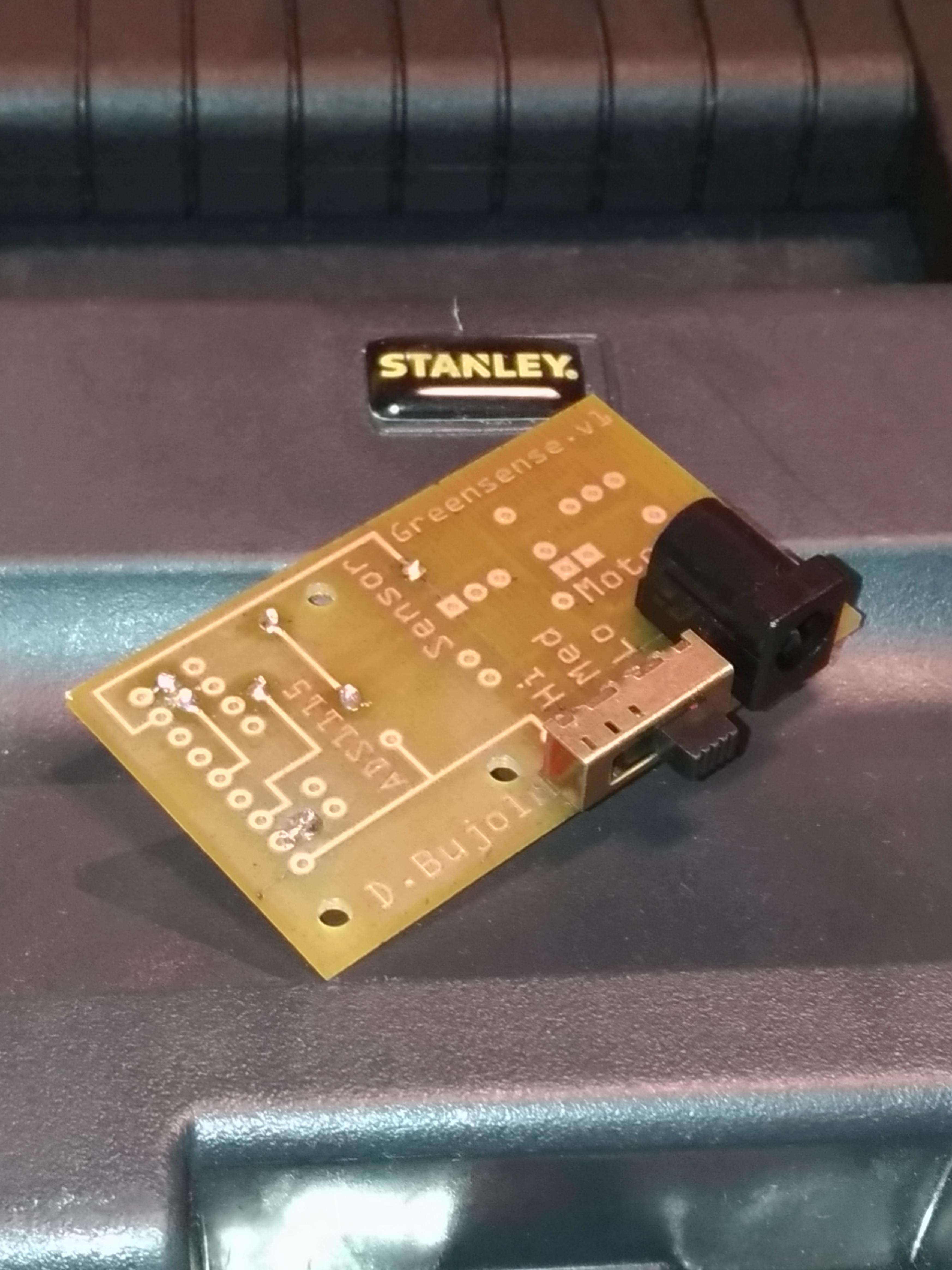
Over the weekend I finished soldering my PCB, here is the result:
Top:
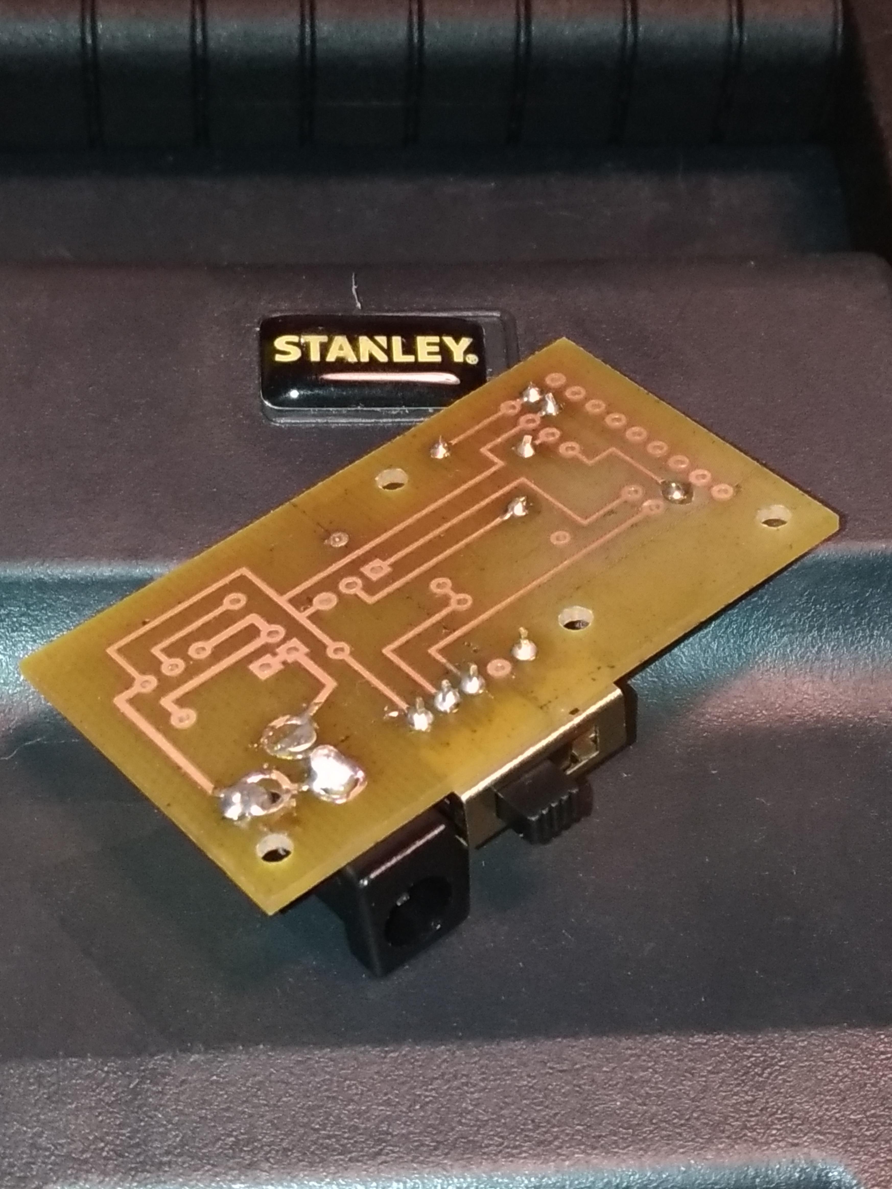
Bottom:
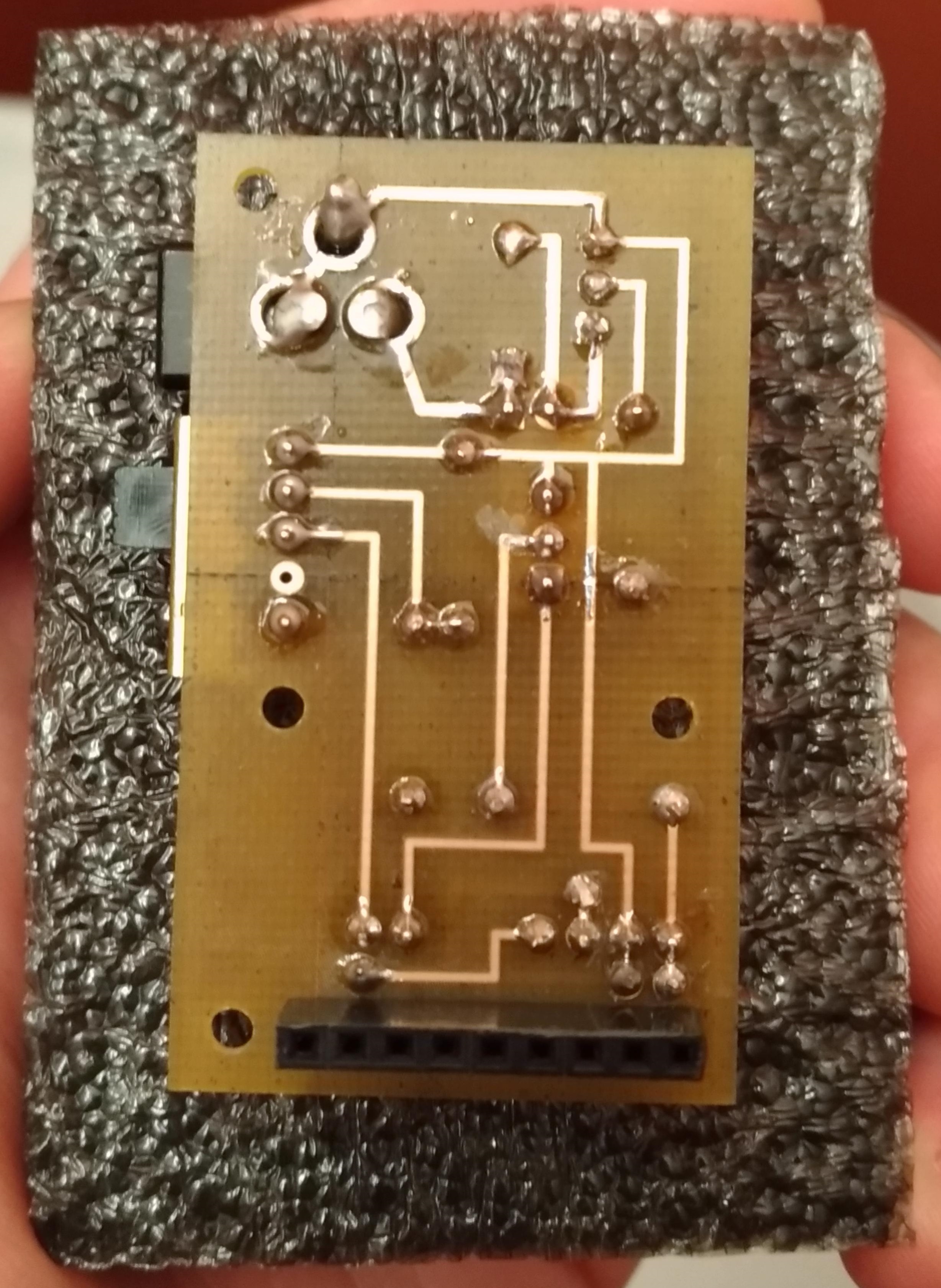
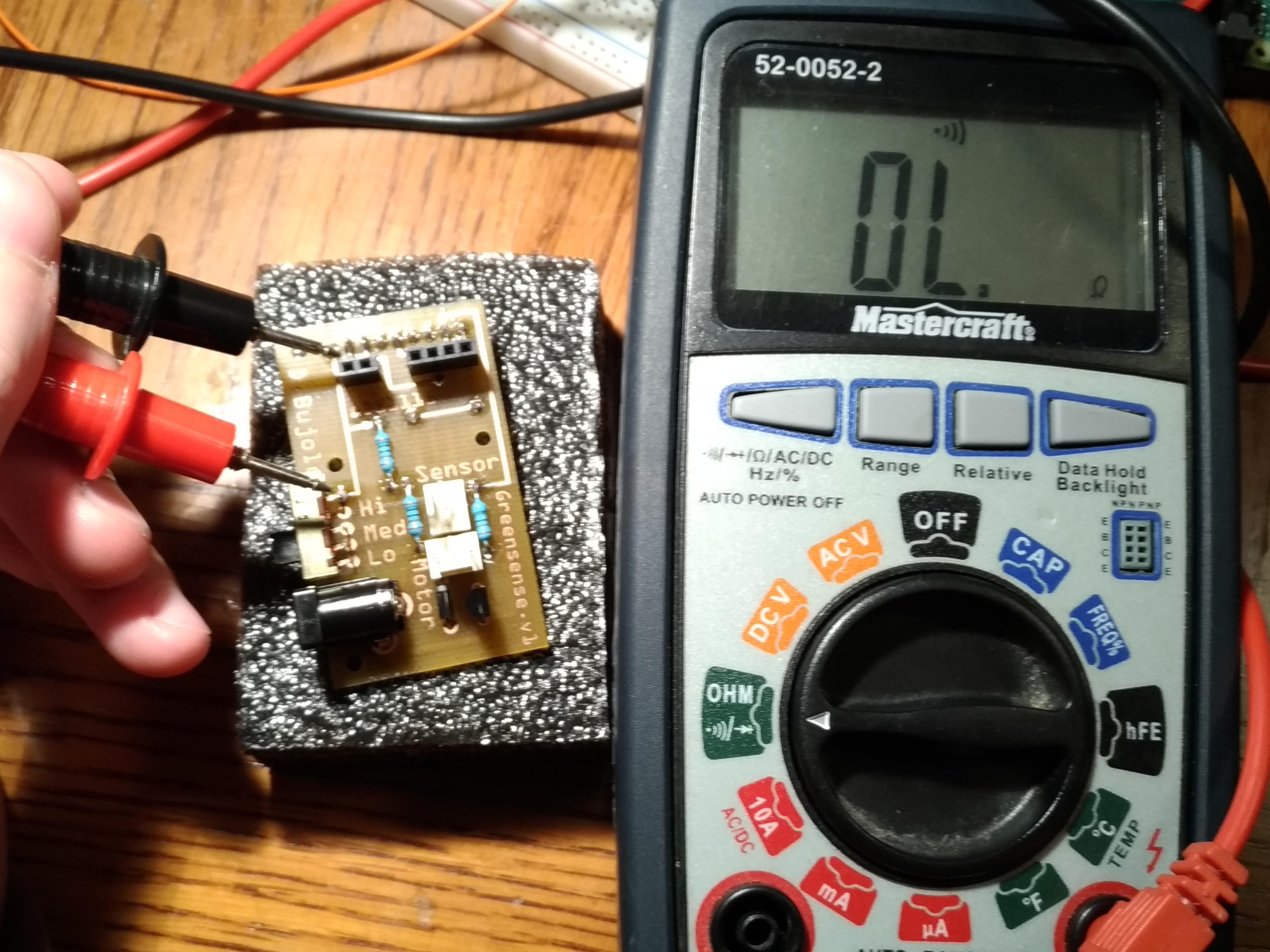
I ran continuity tests on the traces, vias, and between adjacent header pins. Everything passed.
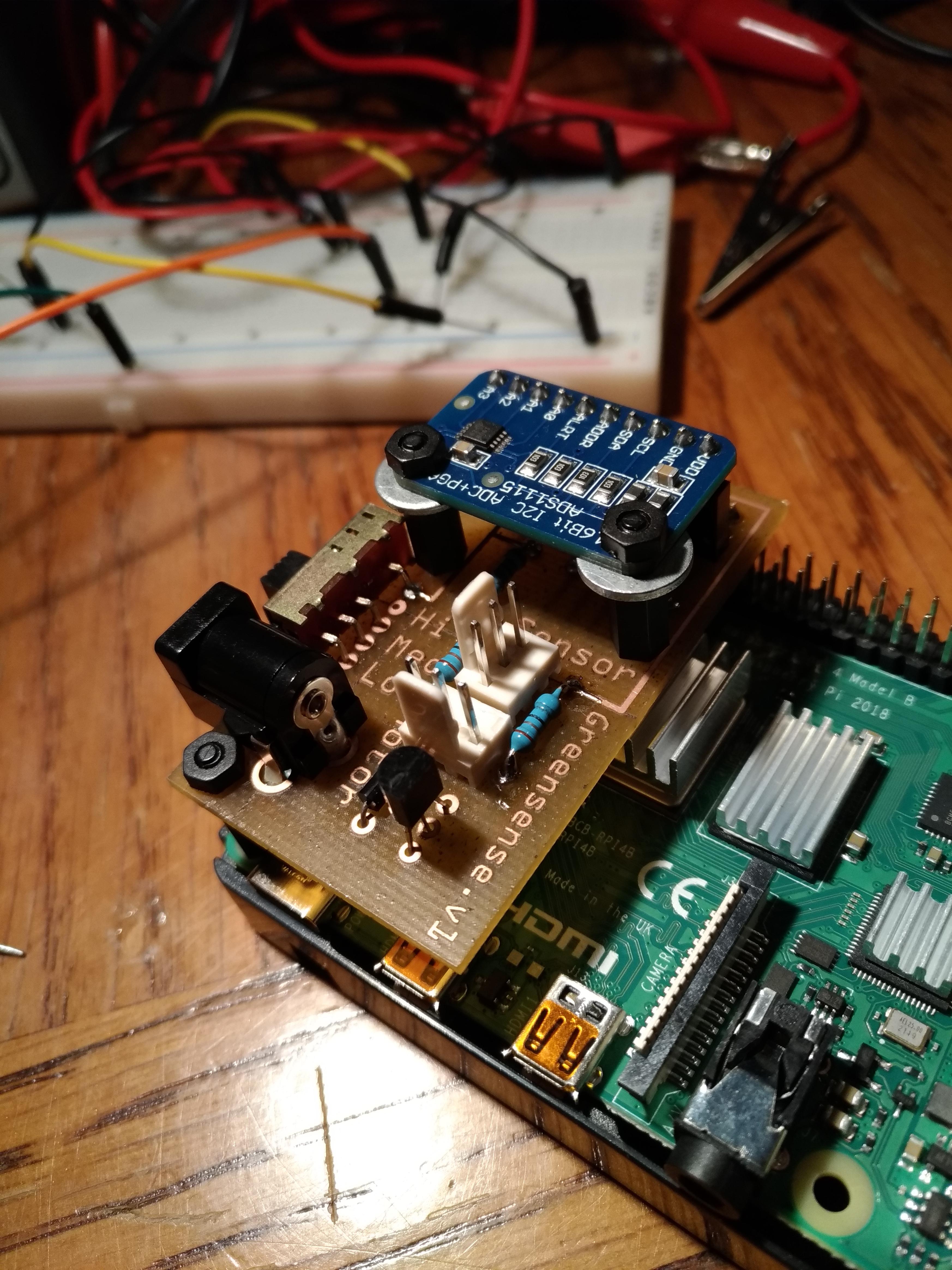
I tested the fit of the completed PCB onto the Pi using some small risers/washers I had on hand.
I am currently on time with my project schedule.
My PCB is fully soldered.
My budget is in the same state as previous weeks (approx. $45 over due to adding ADC and Pi 4 upgrade).
The system is coming together as planned in my project proposal (with the addition of the watering control switch).
Next steps:
I will be testing the PCB with the Pi/sensor during this week to prepare for the next milestone.
Begin the progress report due next week.
We are attending the 3D printing seminar on Tuesday as a class.
I will begin designing the enclosure following the seminar.
October 29, 2019 - Breadboarded Milestone
As you can see from my October 14th blog entry, I previously breadboarded all the individual components (unit testing). I will reassemble the full setup (including the ADC and Pi this time) to demonstarte during Tuesday’s lab.
Complete Breadboard:
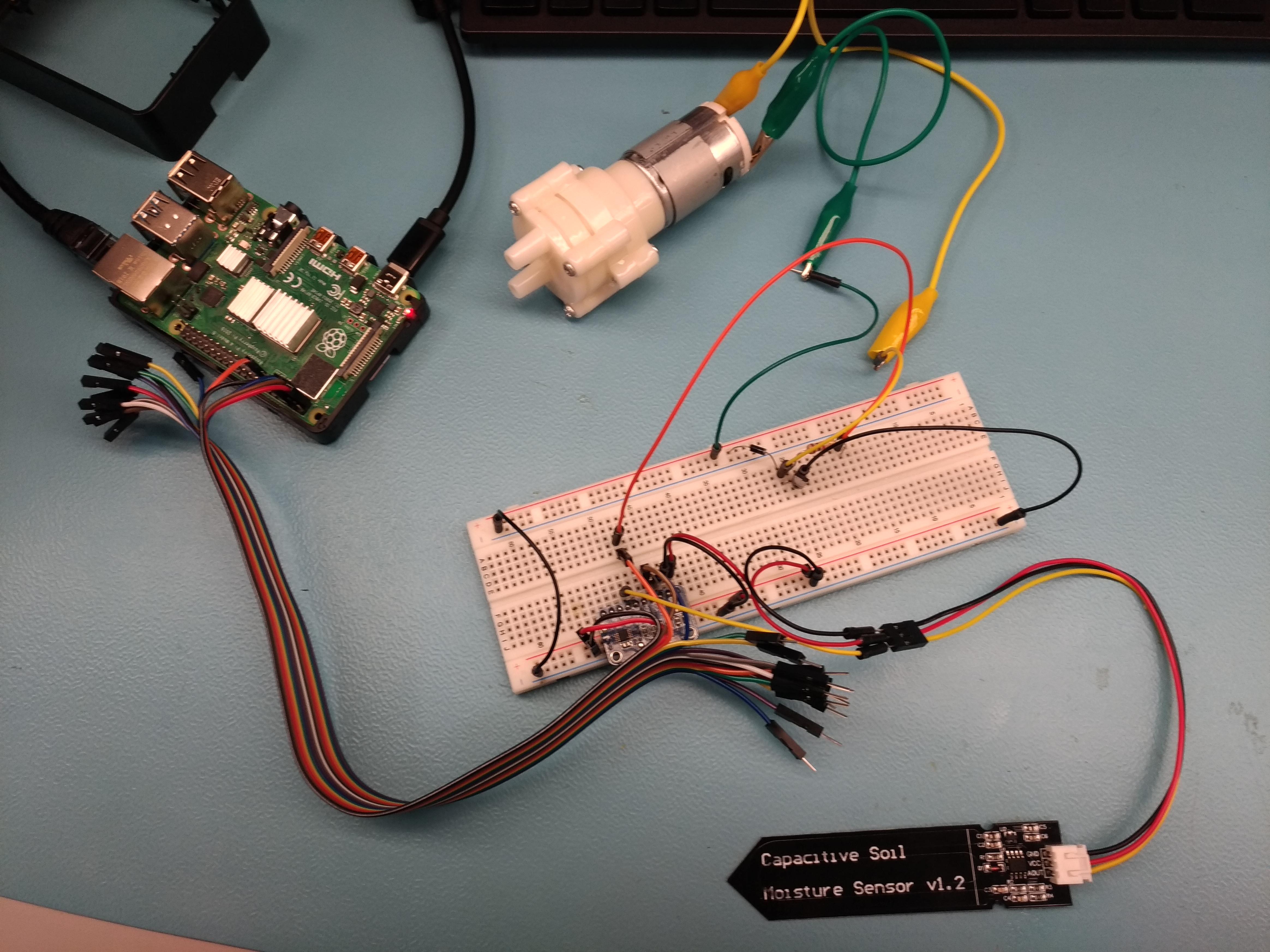
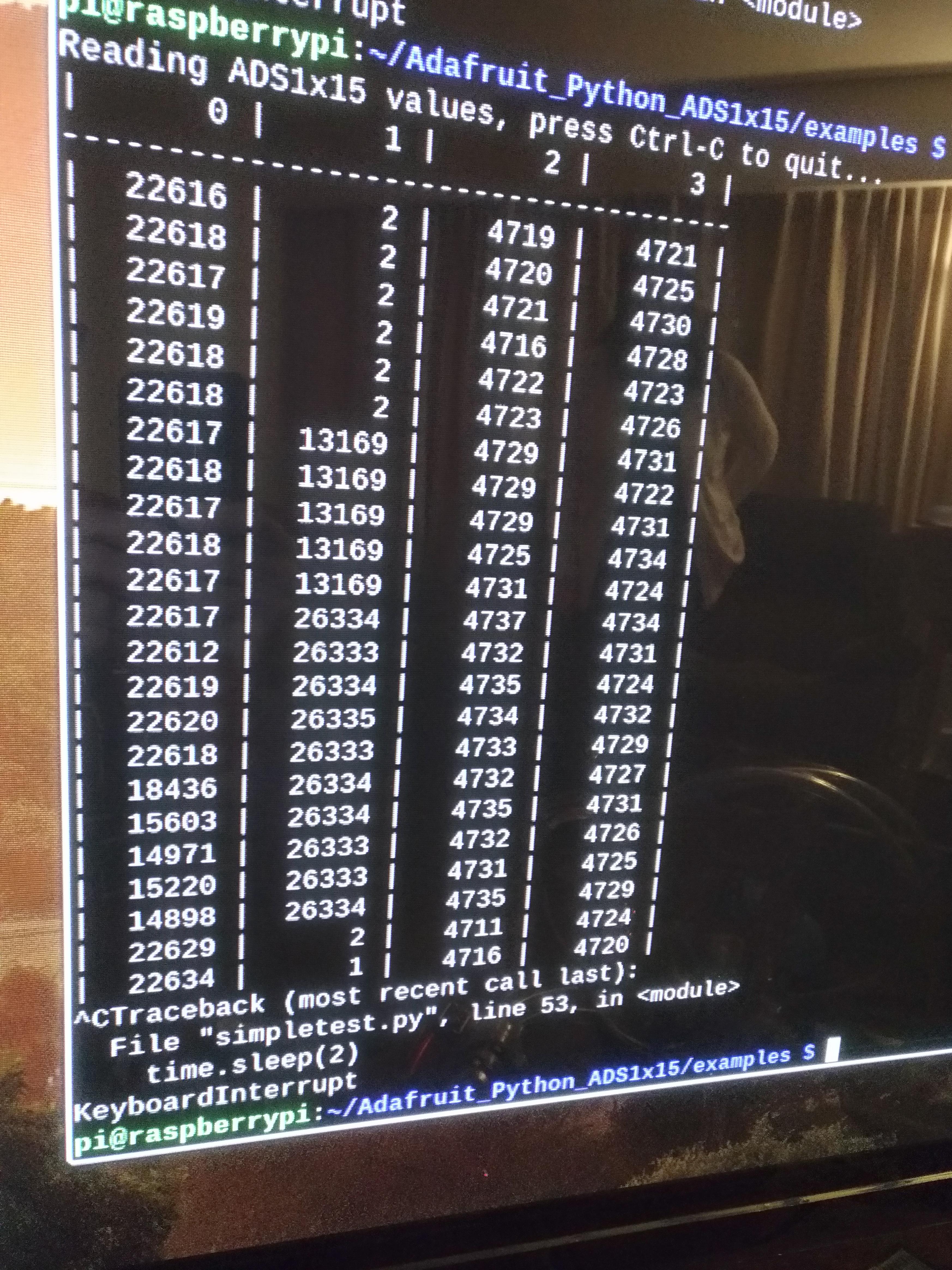
I used libraries/sample code from Adafruit to get the analog readings from the ADS1115 and display them, which can be found here.
Initial Readings (soil sensor in far left column):
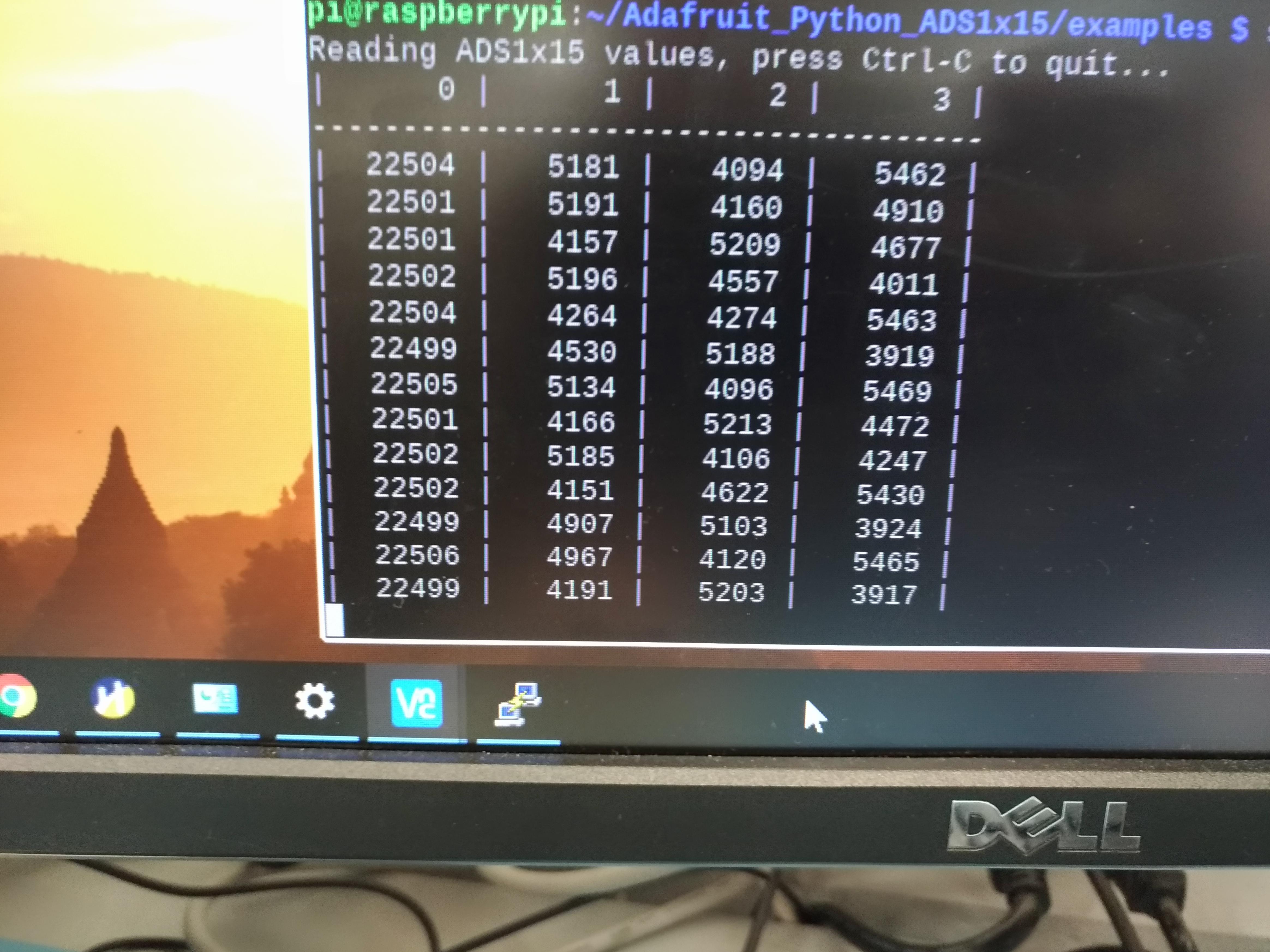
Change in readings:
I am currently ahead of my project schedule.
My breadboarding is complete and I have started soldering. My PCB should be fully soldered in the next few days.
I am still slightly over budget due to adding the ADC and the Pi 4 upgrade. No extra costs/obstacles since the ADC though.
October 27, 2019 - Begin Soldering
I picked up my PCB at the beginning of reading week (forgot to take pictures). Here is my current progress on soldering.
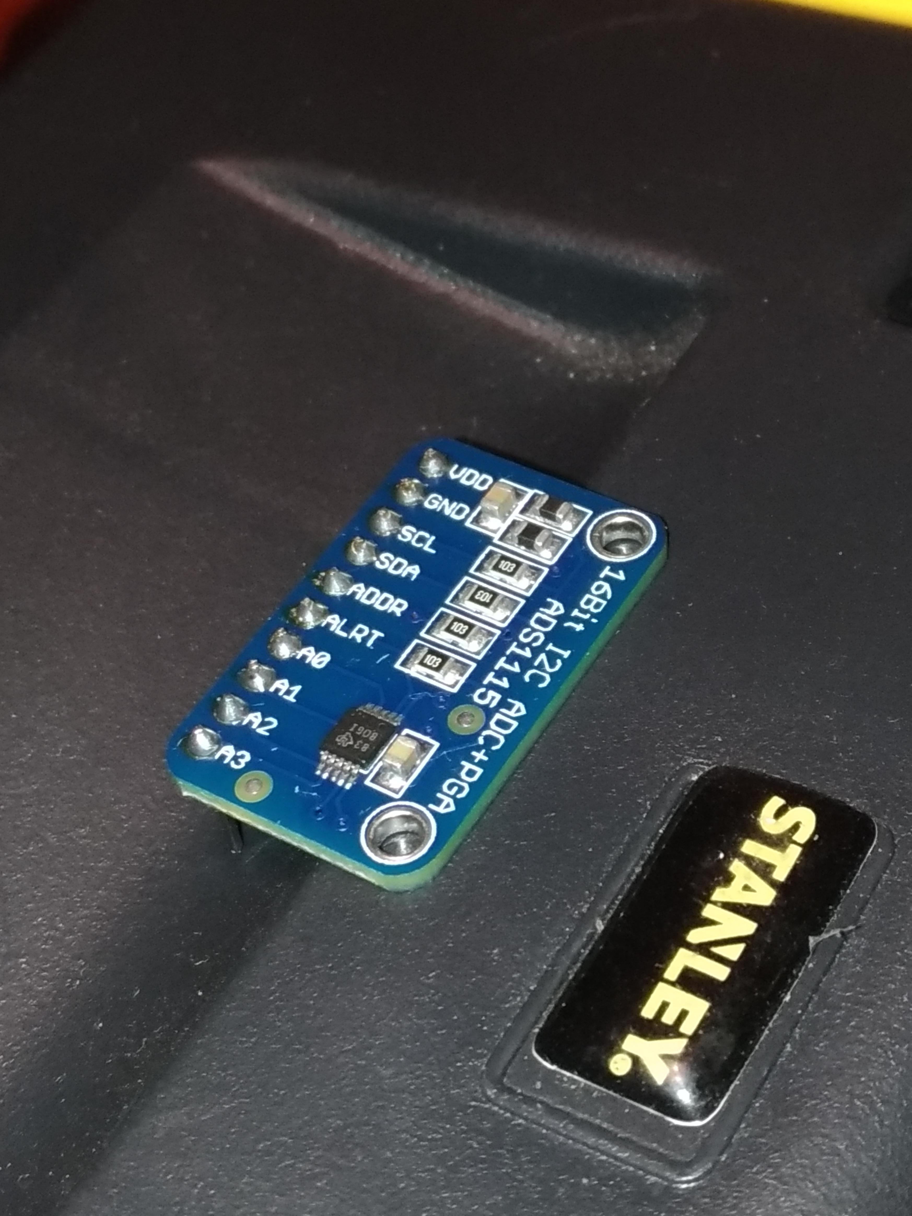
ADS1115:
Vias, Switch, and DC Jack:
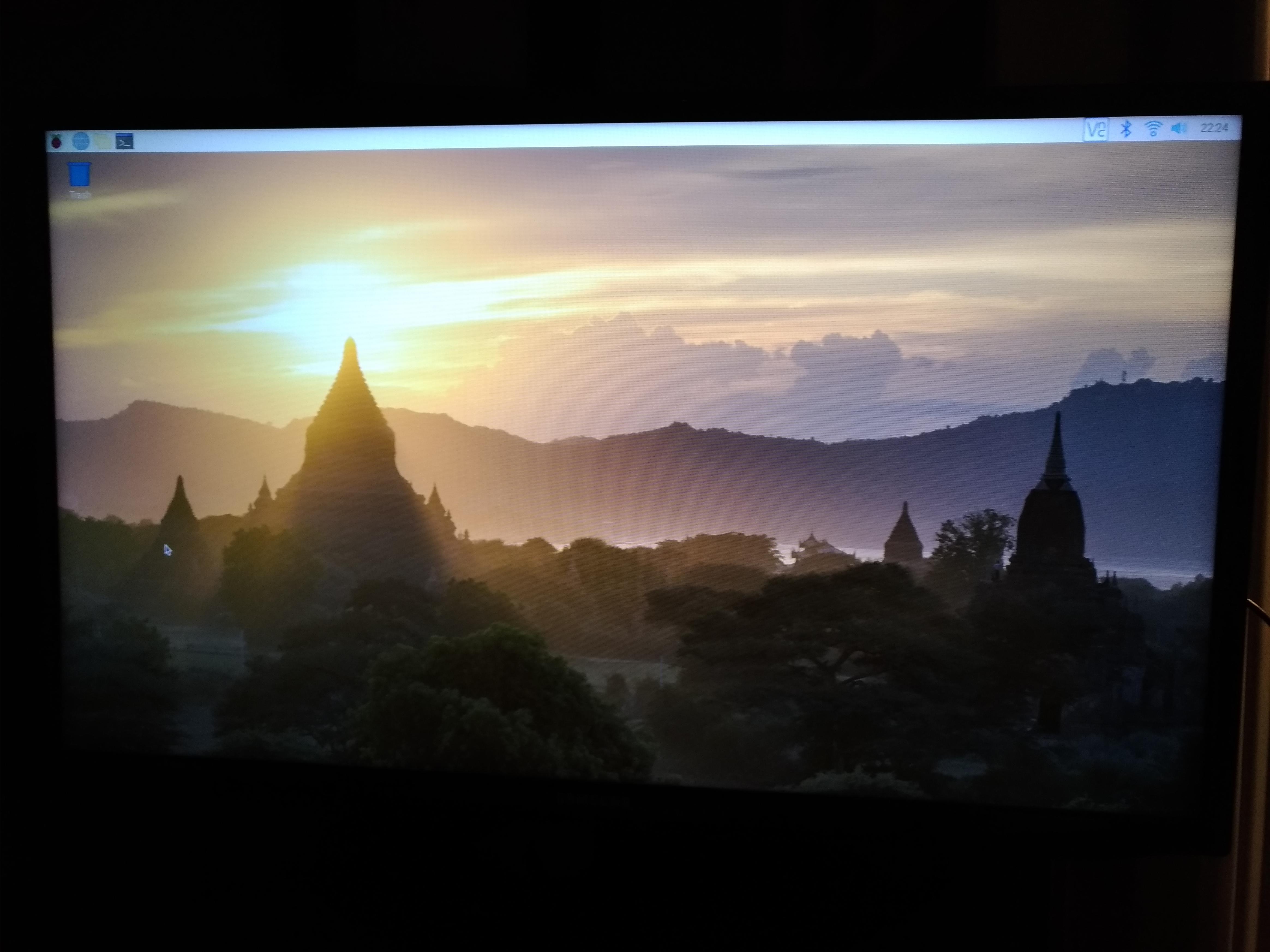
October 22, 2019 - OS Loaded
During reading week I loaded the Raspbian Buster OS and completed the system configuration.
Powering up:
OS loaded:
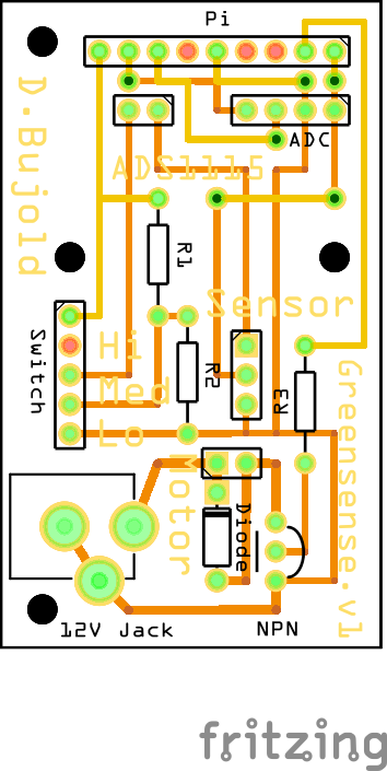
October 17, 2019 - PCB Update
I moved a few components around and managed to reduce the board width to 33mm (original was 39mm). I also turned the ADS1115 around 180 degrees so I could add mounting holes for it.
I’ve sent this design in to the prototype lab to be made.
Updated PCB:
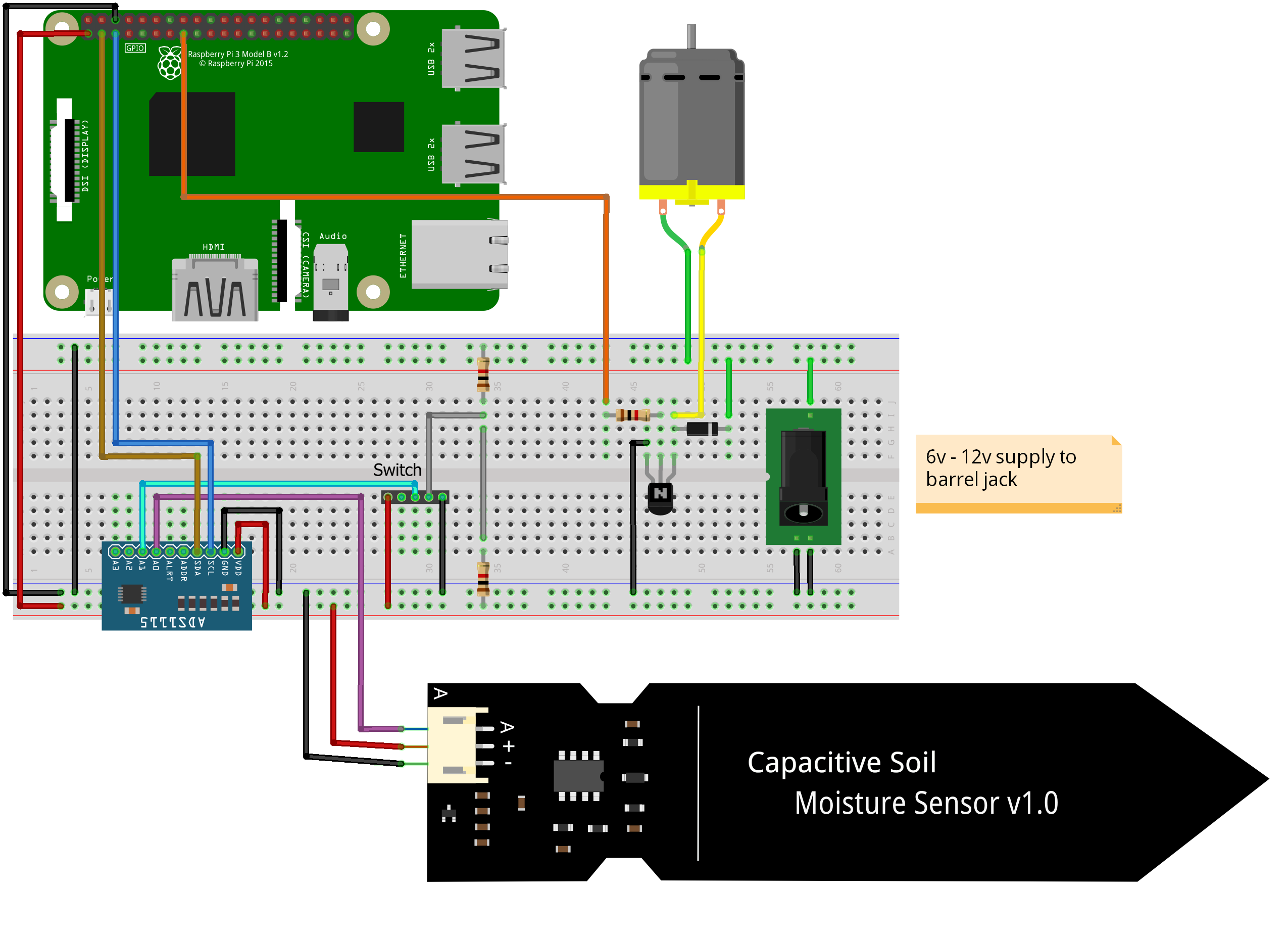
October 15, 2019 - Breadboard and PCB Designed
This weekend I completed my designs using Fritzing. See below…
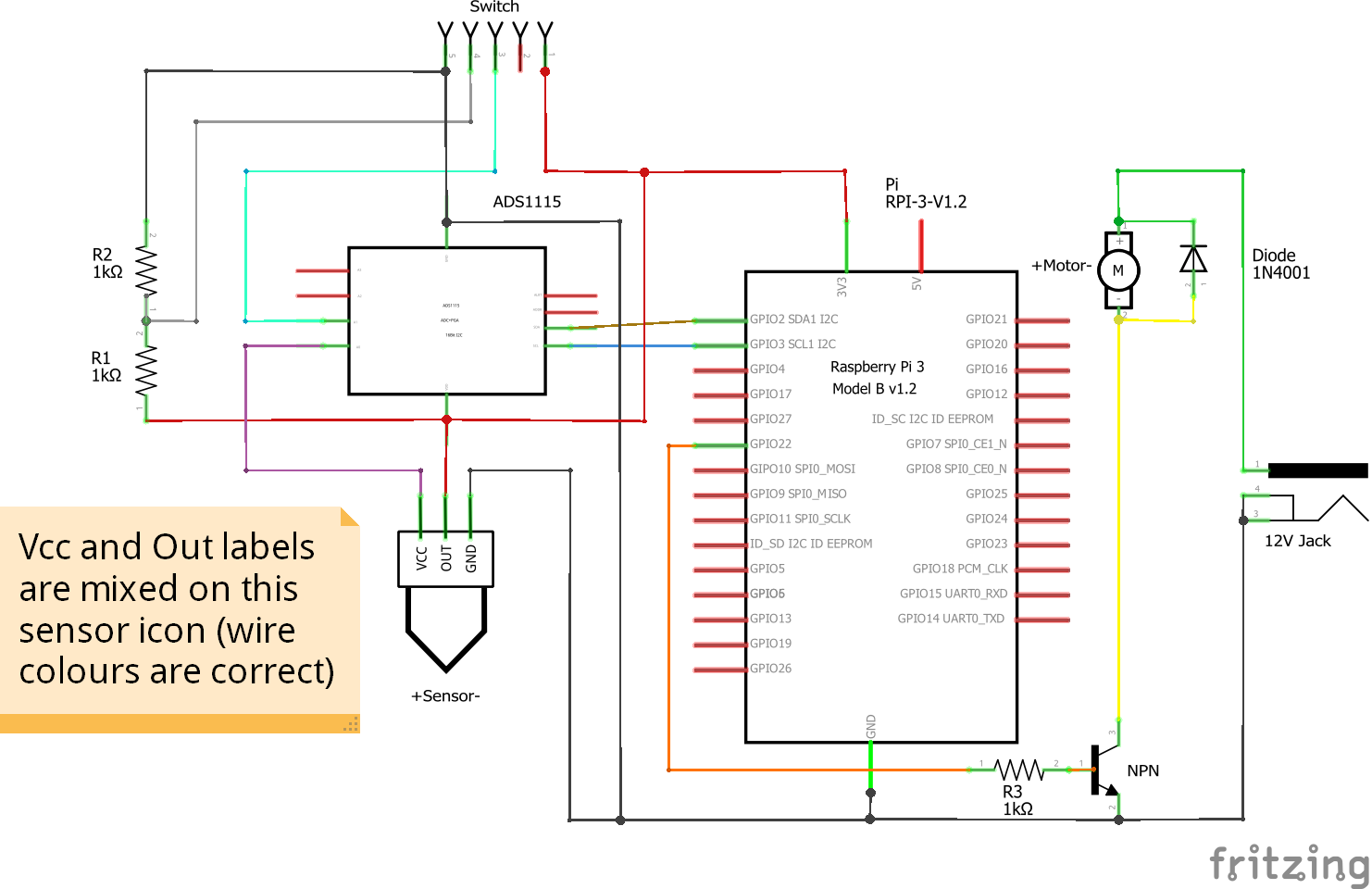
An SP3T switch is displayed as a 5 pin header (Fritzing didn’t have the proper part/none to import).
Kelly recommended using an external power source for the motor (to protect the Pi). I incorporated this by adding a barrel jack for the motor which will connect to a 12v supply.
Breadboard view:
Circuit schematic:
PCB view:
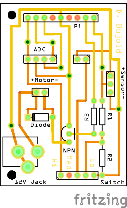
I had to create a separate sketch to design the PCB properly (different sketch than breadboard or schematic). Fritzing wouldn’t allow me to resize the GPIO header or splice the ADC header (for wire routing). I ended up creating my own headers to make this work.
I am currently ahead of my project schedule.
My breadboarding is almost complete and my PCB is designed.
Adding the ADC was a small unforseen obstacle, but I was able to resolve it in a timely and cost effective manner.
I am currently slightly over budget, approx $8 for the ADC and $35 for the Pi 4 (I considered this a necessary upgrade).
October 14, 2019 - Breadboarding Update
Over the last few days I have been testing the individual components of my project by building circuits for them.
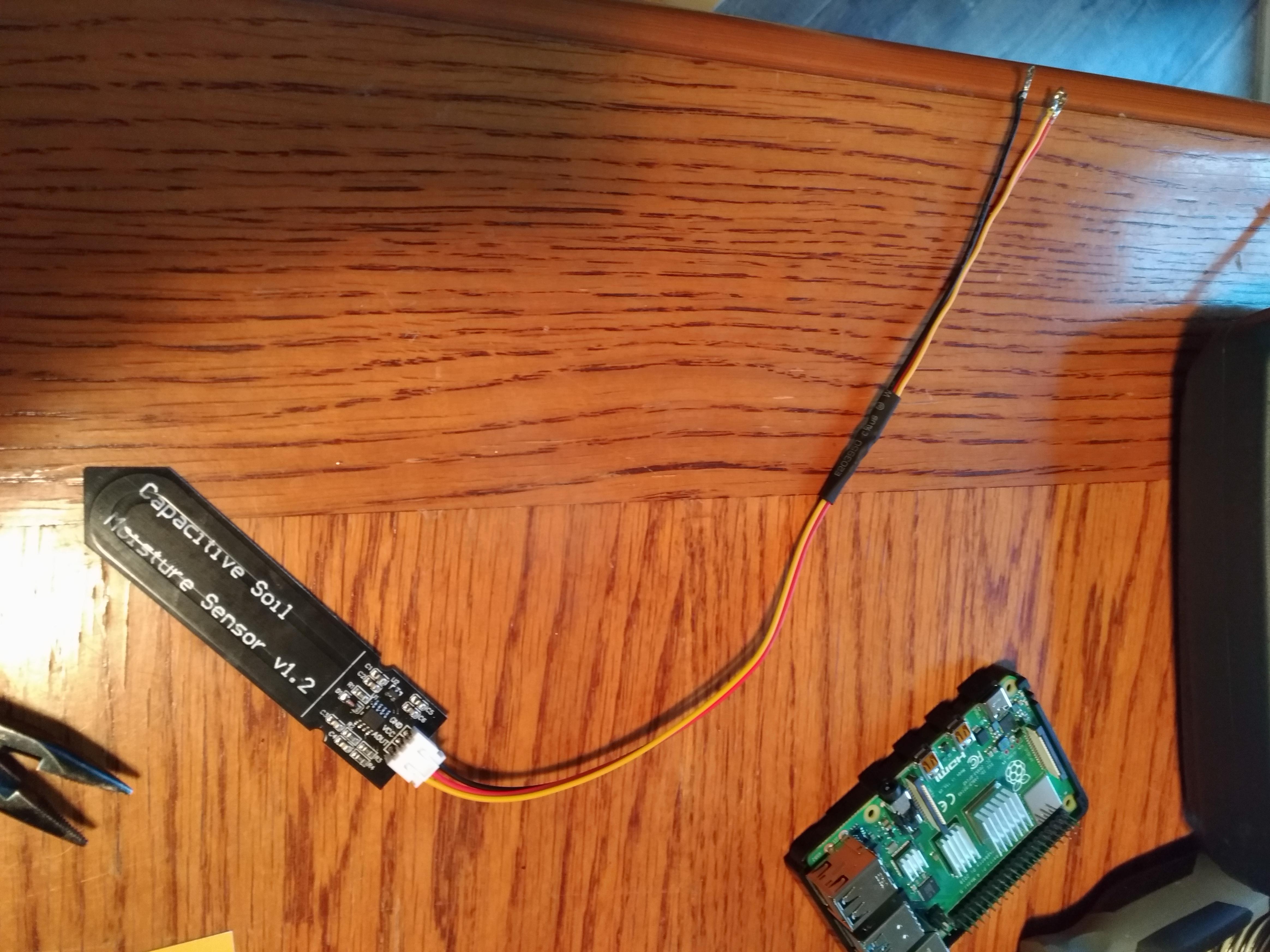
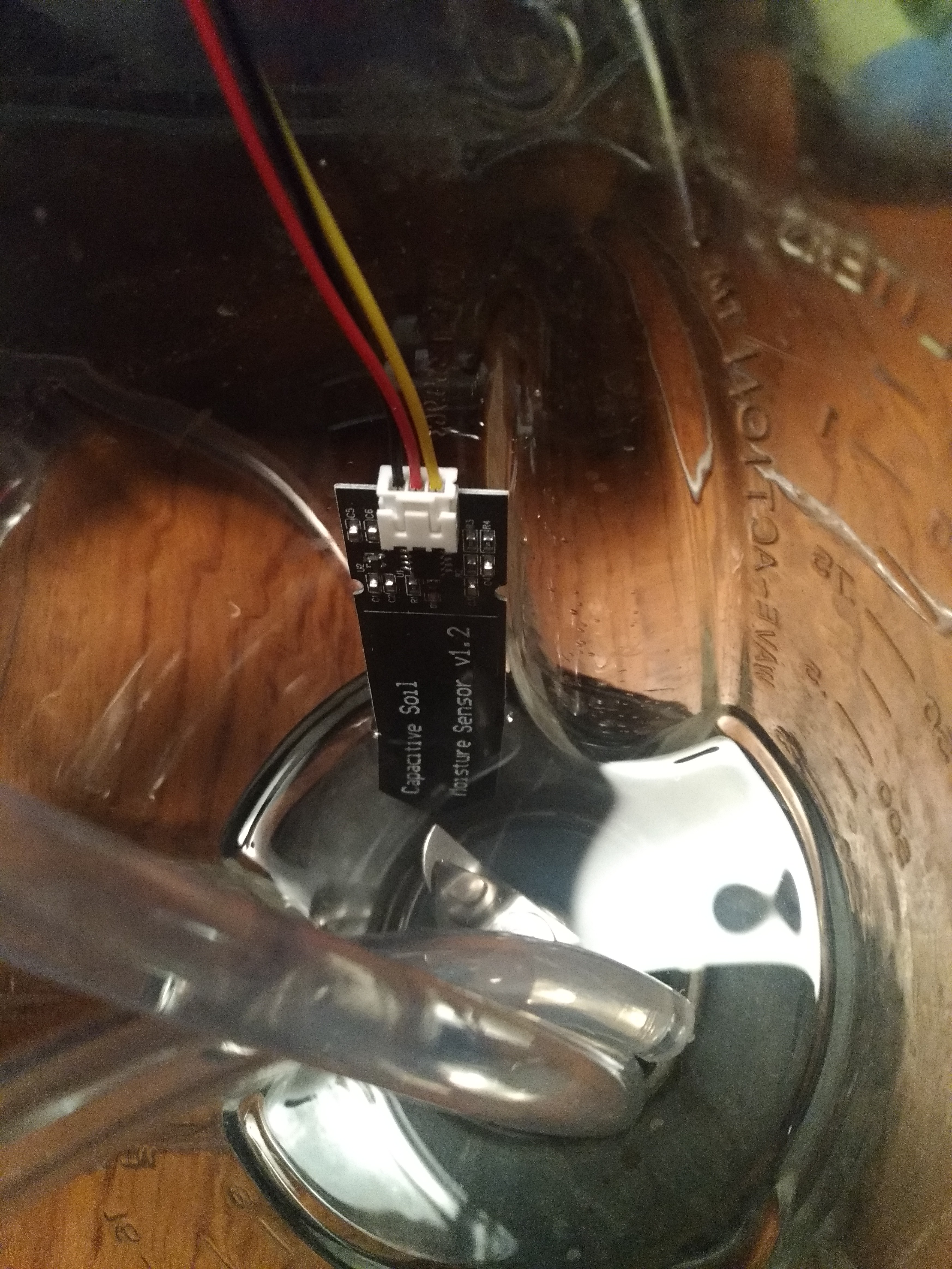
Testing the sensor:
Readings from the sensor (using Arduino for testing):
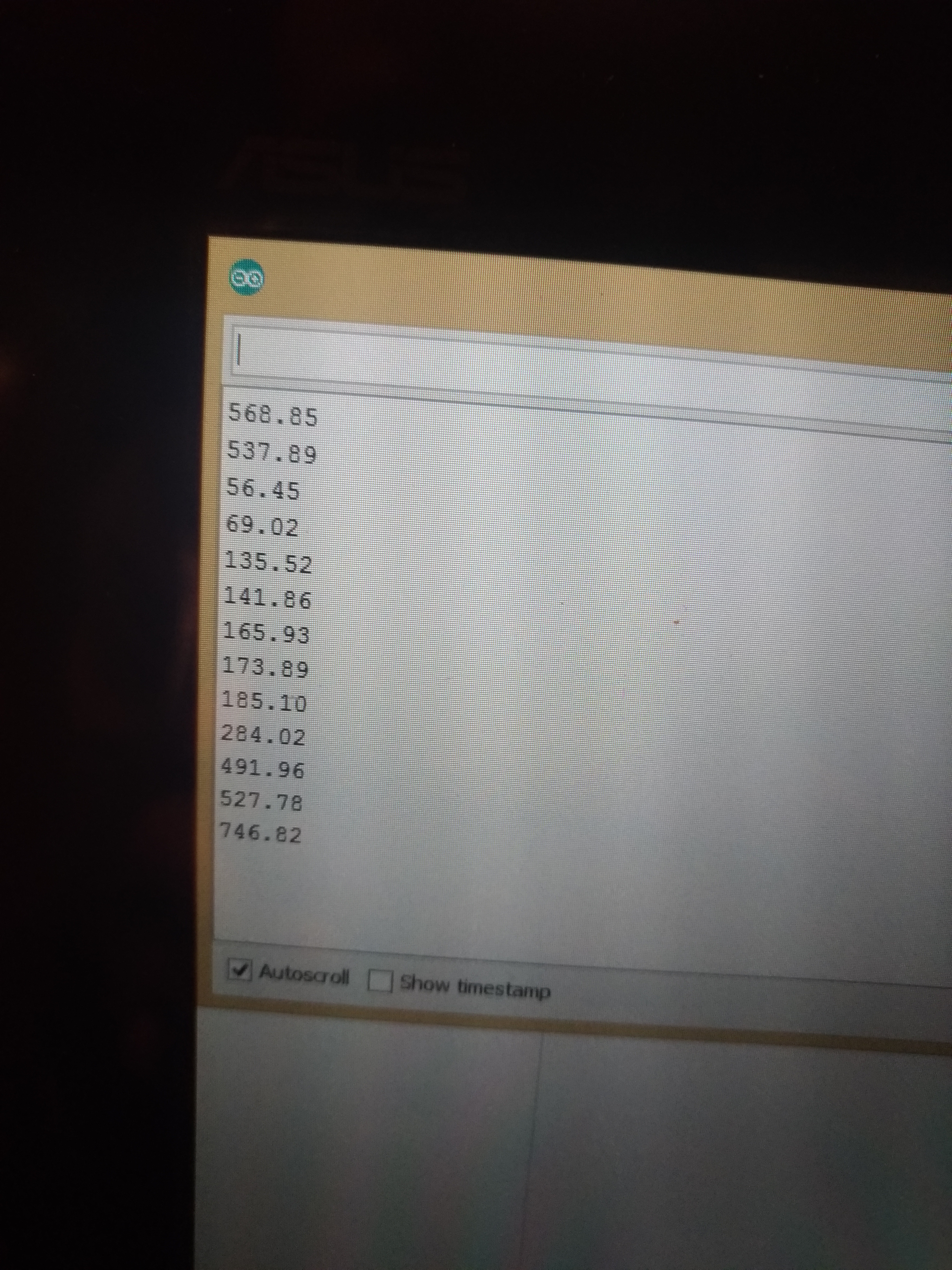
I had to use an Arduino to test the sensor because I didn’t realize the Raspberry Pi has no analog input pins. I will have to add an analog to digital converter to my circuit. I have decided to use the the ADS1115 for its low cost and ease of integration with the Pi. This has been ordered from Amazon (Universal Solder) for $5 + shipping/tax.
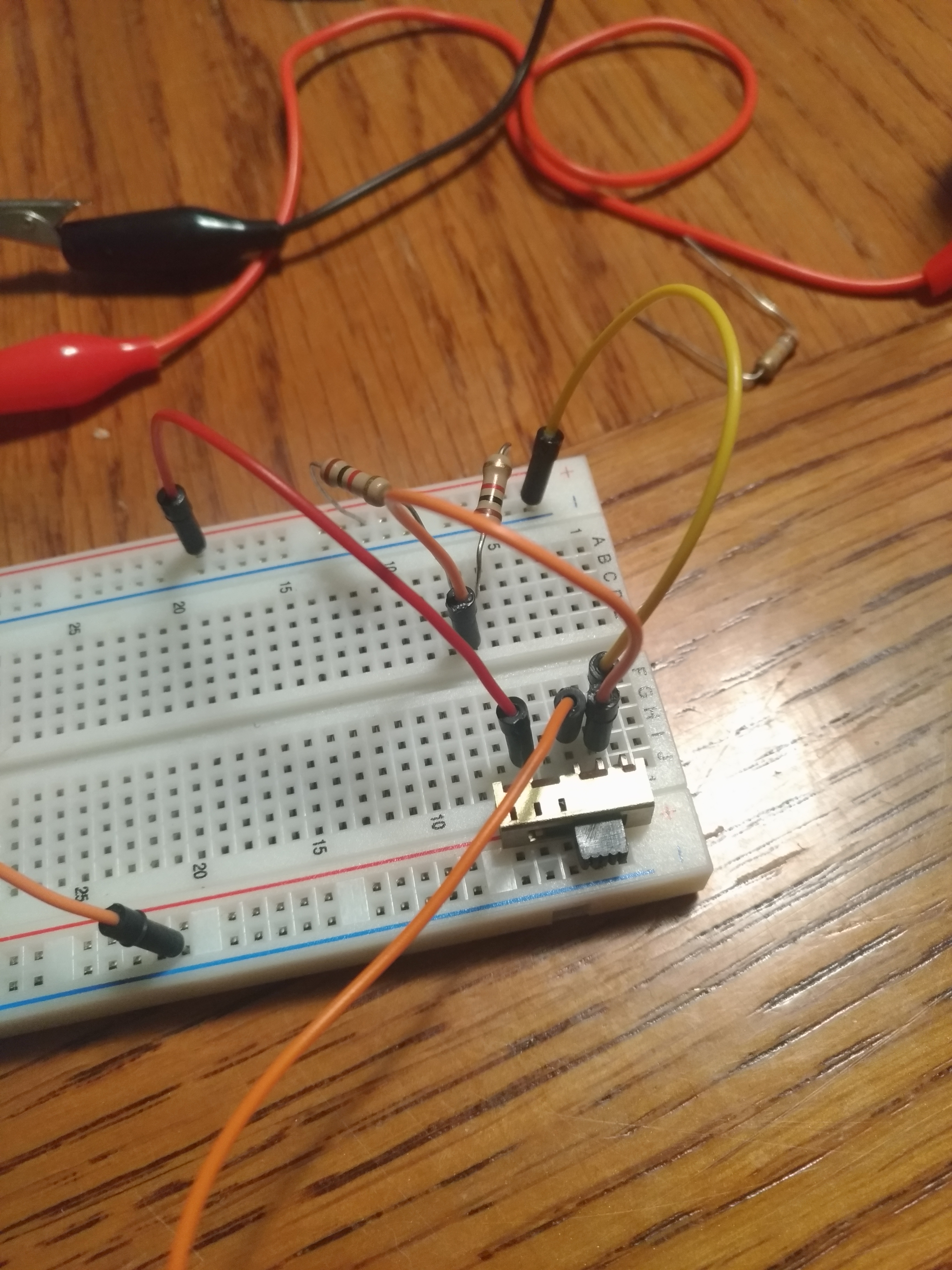
Testing the motor:
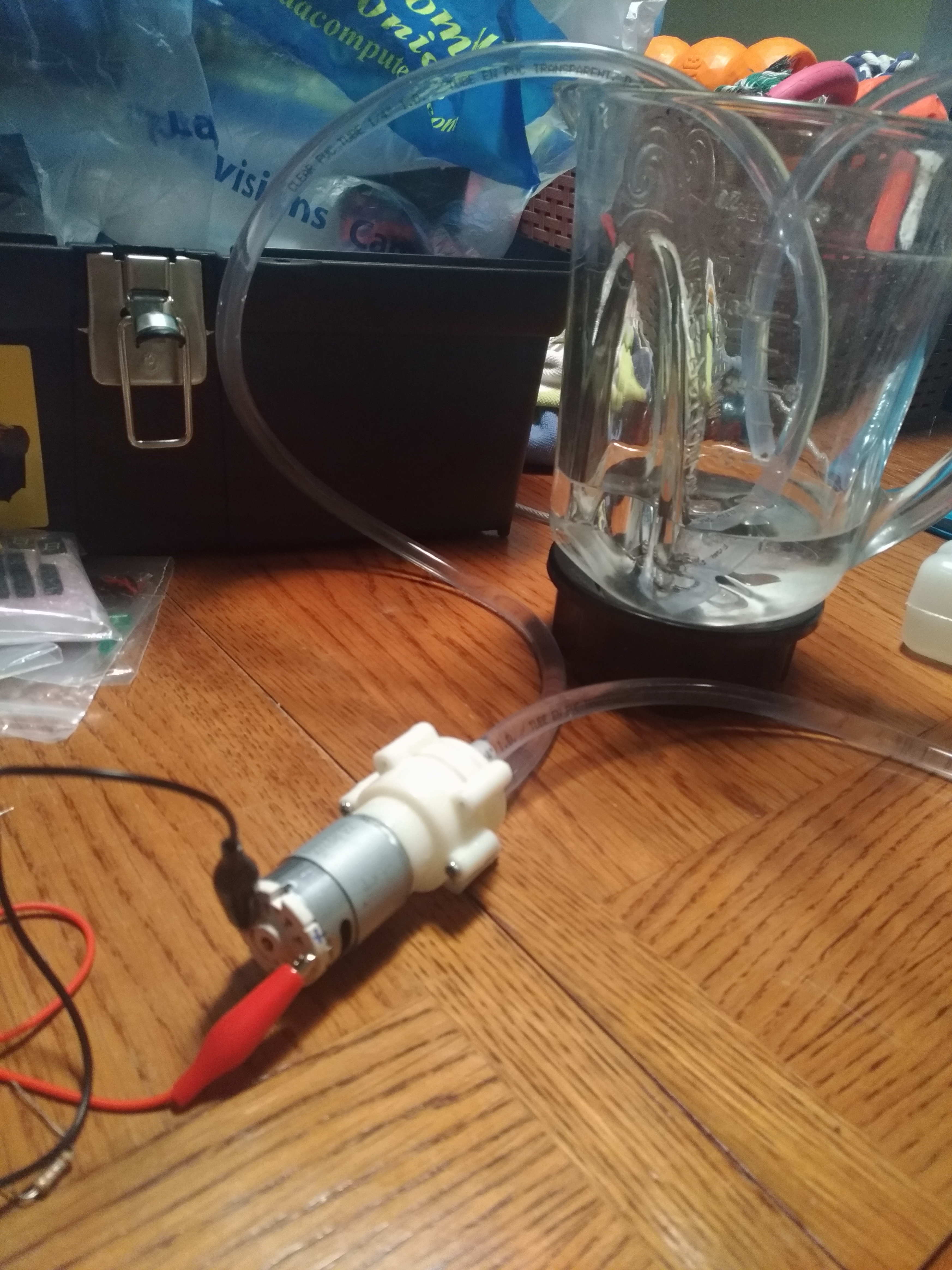
Transistor switching the motor:
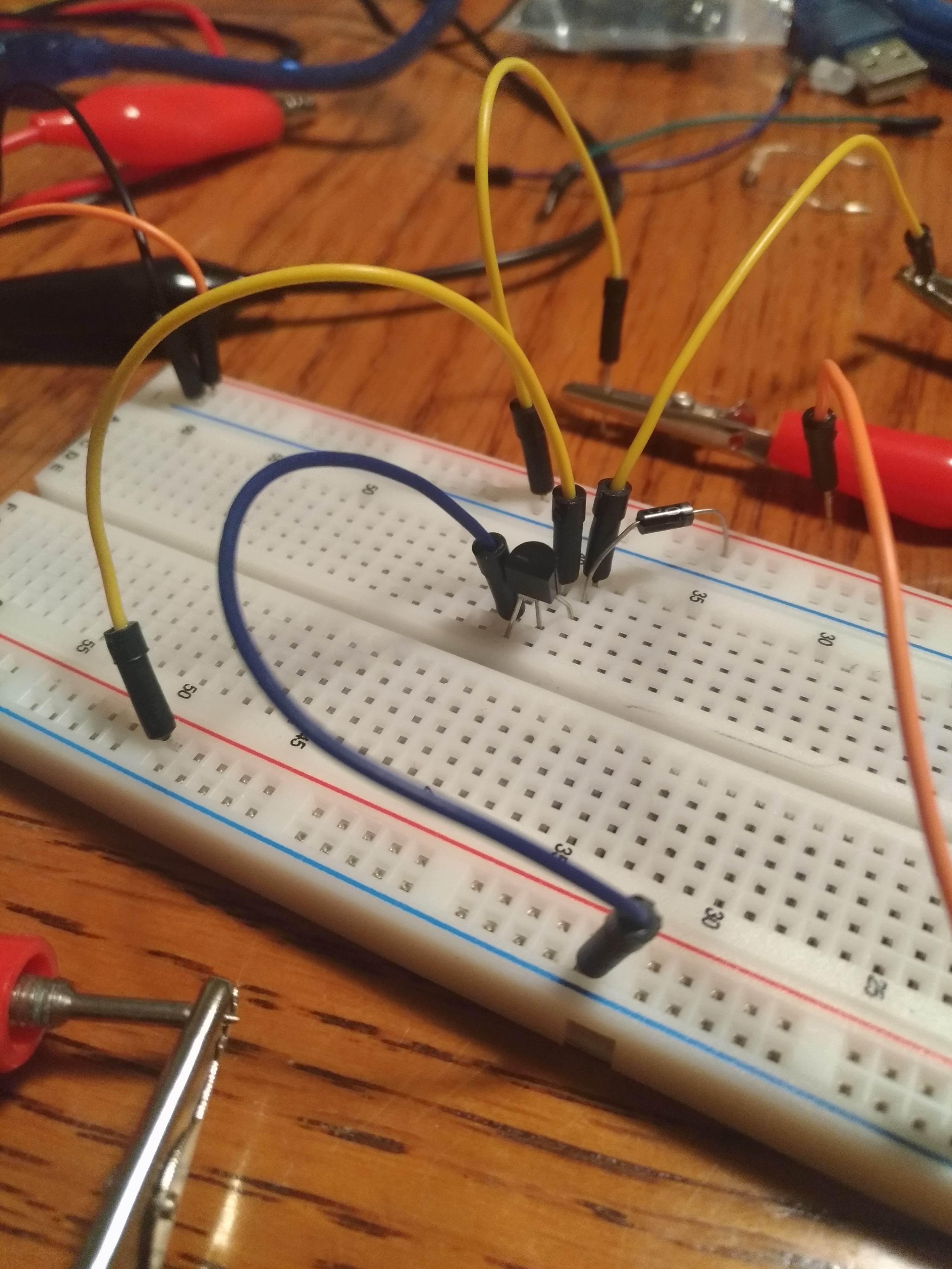
Testing the water control switch:
I decided to add in this water control switch. It will provide users with selection of 3 different watering levels depending on their plant. This was one of the features Valeria said would be nice to have.
October 8, 2019 - Show Acquisitions
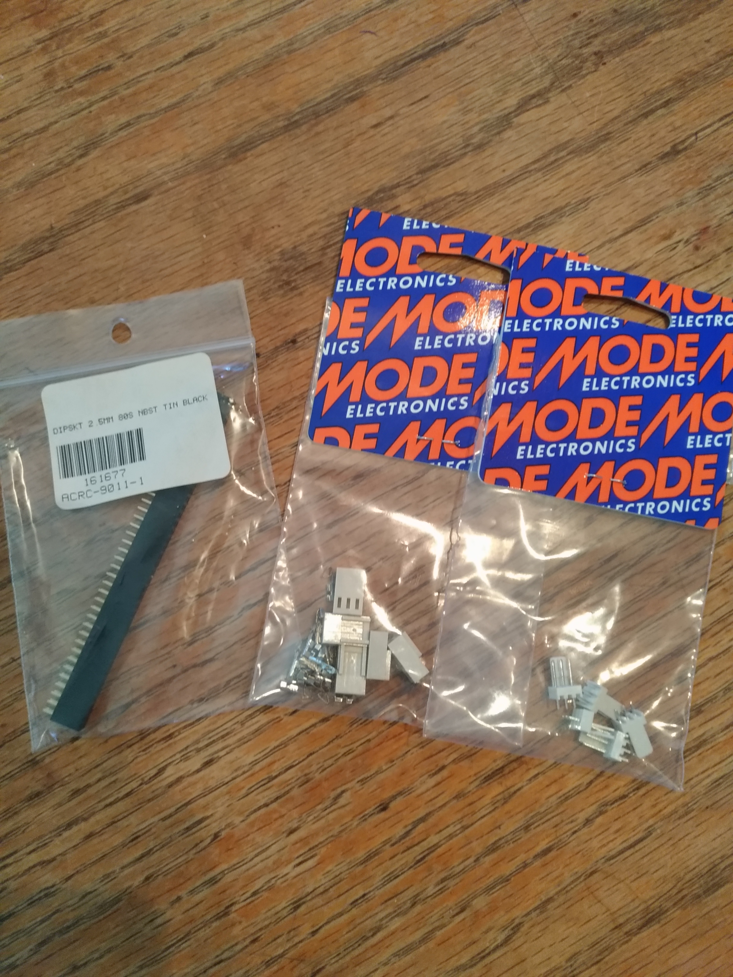
I realized it will be difficult to use these fan connectors on the PCB as they will require through hole plating. Need to exchange these for breakaway header pins.
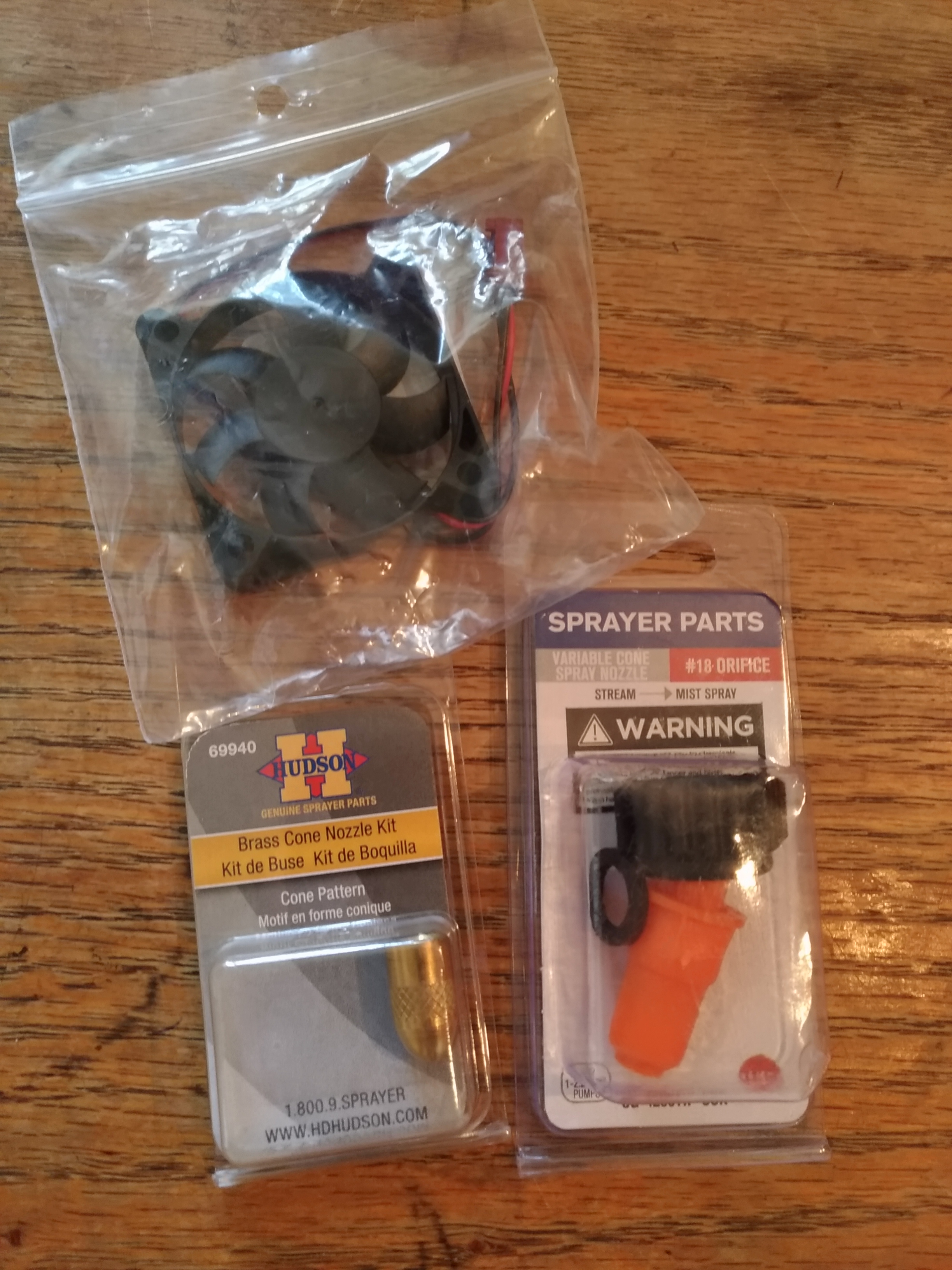
October 4, 2019 - Parts Pickup
Picked up a GPIO header, and 3 pin fan connectors (male/female) from Sayal Electronics. Picked up a spray nozzle and small fan from Princess Auto today.
My Amazon order also came in the mail today (Pi, sensor, and pump).
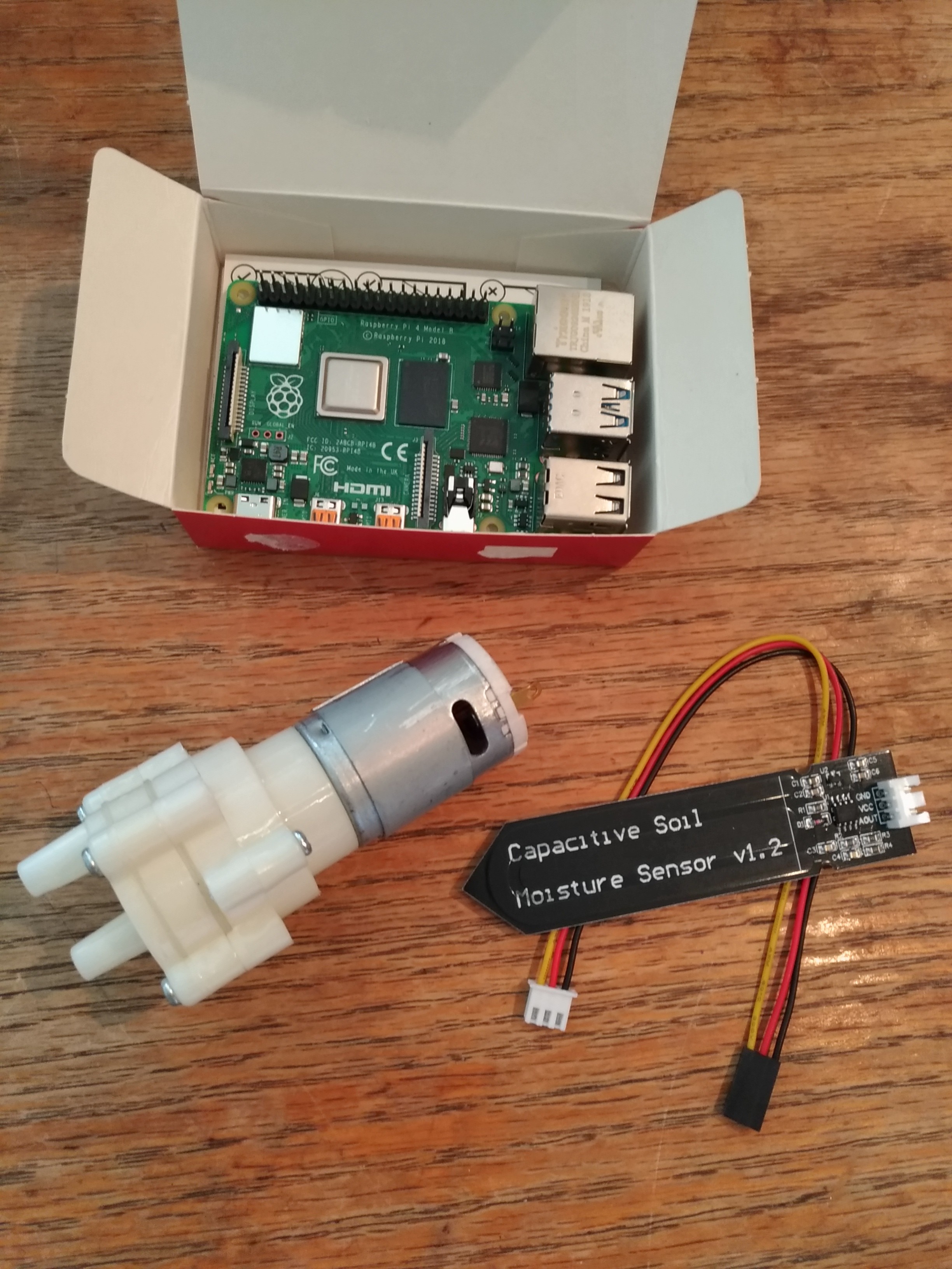
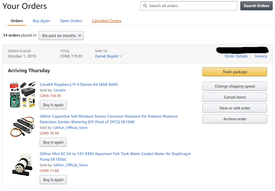
October 1, 2019 - Parts Ordered
The Raspberry Pi 4, capacitive soil sensor, and diaphragm pump have been ordered from Amazon:
I will be picking up some of the other components (headers, jumper connectors, spray nozzle, fittings, etc) later this week.
I have decided to choose the Raspberry Pi 4 instead of the 3 B+. Over the last week I have done some research/comparison of the two models. The Pi 4 has a noticeable edge over its predecessor in processing power, memory, GPU performance, microSD card read/write speeds, and networking speed. All of this for a modest price increase. The 4 made more sense for future proofing and long term reusability.
September 24, 2019 - Budget Due
Click to see the projected budget
Need to discuss with the professor today whether to use a relay, transistor, or code to turn the effector on/off.
Kristian has suggested speaking to Kelly or Vlad regarding this.
Decided on the capacitive moisture sensor instead of resistive, due to more accurate readings and corrosion resistance. I have sourced the Gikfun EK1940 from Amazon.
I will also be incorporating a pump/nozzle system to spray water on the soil when moisture readings are low. I will be using the Gikgun EK1856C from Amazon.
September 17, 2019 - Schedule Due
Here you can view the proposed project schedule pdf.
Repository edit: Proposal and schedule files moved into nested folders inside Documentation folder.
Met with our project sponsor (Valeria) and received great feedback regarding different features we can implement/how to implement. Meeting report to follow soon.
September 10, 2019 - Proposal Due
Here you can view the submitted project proposal pdf.
September 3rd, 2019 - Project Selection
Repository created at 2:42 PM.
Group has been selected. Ryan, Aiden, and Daniel for 317 Hardware and 319 Software. Selected project is Greenhouse.